AMOT G Series Installation, Operation And Maintenance Manual
Hide thumbs
Also See for G Series:
- Operation and maintenance manual (80 pages) ,
- Operation, installation, and maintenance manual (94 pages)

Related Manuals for AMOT G Series


Summary of Contents for AMOT G Series
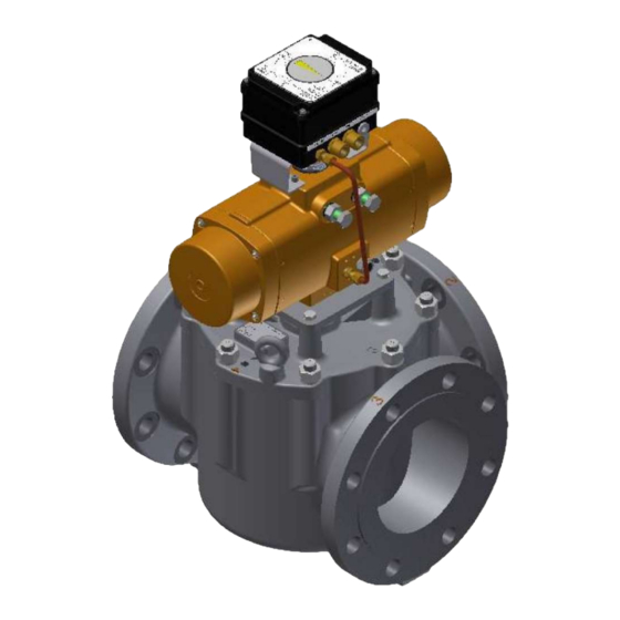
- Page 1 Model G Valve (Pneumatically Actuated) Installation, Operation and Maintenance Manual Doc No: OMMGGP00185 Revision: 5 Date: MAY 2019...
-
Page 3: Table Of Contents
Contents Introduction ...................... 5 Scope of Manual ............5 Safety................5 Product Support ............. 6 Typographical Conventions ..........6 European Union Directives..........7 System Overview ..................... 9 Description ..............9 Identification of Model Number ........11 Modes of Operation ............12 System Components ............. - Page 4 Service Intervals ............70 12.3 Minor Service (every 2 years) ........70 12.4 Major Service (every 4 years) ........71 12.5 AMOT Field Service ............73 Technical Data ....................74 13.1 Selection of G-Valve options .......... 74 13.2 Technical Specifications ..........83 Rev 5 –...
-
Page 5: Introduction
Introduction Section 1 Introduction Contents Para Page Scope of Manual ................5 Safety ..................5 Product Support ................6 Typographical Conventions ............6 European Union Directives ............7 1.5.1 EU Machinery Directive ............7 1.5.2 EU Pressure Equipment Directive ........7 Scope of Manual This manual contains the information to install, operate and maintain the pneumatically operated G Valve system. -
Page 6: Product Support
Introduction WARNING A Warning identifies a step in a procedure that can cause injury to people. The warning identifies the hazard and lists the precautions that must be taken before the next step of the procedure is done. CAUTION A Caution identifies a step in a procedure that can cause damage to equipment. -
Page 7: European Union Directives
European Union Directives 1.5.1 EU Machinery Directive The AMOT Model G Valve, as a component, is not considered to be a machine. To fully comply with the Directive however, the machine into which the valve is installed must comply with the requirements of the machinery directive before the valve is put into operation. - Page 8 Introduction Rev 5 – MAY 2019 OMMGGP00185...
-
Page 9: System Overview
System Overview Section 2 System Overview Contents Para Page Description ................. 9 2.1.1 Features ................9 2.1.2 Typical Applications ............10 Identification of Model Number ............ 11 Modes of Operation ..............12 System Components ..............12 Description The G Valve and its supporting equipment are designed for the control of fluid temperature by ‘diverting’... -
Page 10: System Overview
System Overview 2.1.2 Typical Applications Lubricating Oil Temperature Control Lubrication oil temperature control is normally configured in a mixing application controlling the return temperature to the heat load. The temperature is normally measured as close as possible to the sump return. Jacket Water Cooling Jacket water cooling in diverting applications regulates the outlet coolant... -
Page 11: Identification Of Model Number
System Overview Identification of Model Number Example code Code Description Nominal Bore Size Comments 2 inch (DN50) High flow only 3 inch (DN80) Valve 4 inch (DN100) Size 5 inch (DN125) Standard flow only 6 inch (DN150) 8 inch (DN200) 10 inch (DN250) Standard flow only Model Type... -
Page 12: Modes Of Operation
System Overview Modes of Operation Fig 1 Modes of Operation (viewed from above – actuator end) System Components The components of the G Valve control system are listed below. Refer to Section 10 (System Integration) for the interconnection details. Component Further information Valve body... - Page 13 System Overview Component Further information 8064A Electro pneumatic converter Section 6, page 55 Produces pneumatic output from 4 – 20 8064A manual mA electrical control signal. 8064C Electro pneumatic converter Section 6, page 55 Produces pneumatic output from 4 – 20 Installation, mA electrical control signal.
- Page 14 System Overview Rev 5 – MAY 2019 OMMGGP00185...
-
Page 15: Valve Body
Valve Body Section 3 Valve Body Contents Para Page Description ................15 Installation ................15 Operation ................. 15 Maintenance ................16 3.4.1 Dismantle and Assemble ..........16 3.4.2 Recommended Spares ............. 19 Description The G Valve is a compact and rugged 3-way control valve designed for temperature control using ‘diverting’... -
Page 16: Maintenance
Valve Body Maintenance 3.4.1 Dismantle and Assemble Fig 2 General Arrangement Dismantle Valve (refer to Fig 3, page 17) It is possible to dismantle the valve without the need to remove it from the pipework as follows: Note Ensure replacement seals are available before dismantling the valve (refer to Section 3.4.2 for spare parts detail). - Page 17 Valve Body Fig 3 Section View (04GGH illustrated) Switch off and isolate power to the actuator. Using the handwheel, turn the valve to the low temperature position. Note position of actuator in relation to valve body. WARNING If an actuator is removed from a valve fitted in a live system, the valve rotor may rotate uncontrollably in the body.
- Page 18 Valve Body 12. Remove and discard the upper and lower shaft O Rings (8 & 9). 13. Inspect the valve internals for wear, damage and cleanliness. Clean and replace if necessary. Reassemble Valve (refer to Fig 3, page 17) 14. Apply Molykote ®...
- Page 19 Valve Body 3.4.2 Recommended Spares It is recommended that all the spares listed below are replaced each time the valve is disassembled. These are available in kit form (see servicing schedule, Section 12). Note All O rings are Viton Valve Type 02GGH and 03GGS (Fig 3, page 17) Description Part Number (qty) O Ring, Cover...
- Page 20 Valve Body Valve Type 08GGH (Fig 3, page 17) Description Part Number (qty) O Ring, Cover 43603L002 (1) O Ring, Top Seal 43607L002 (1) O Ring, Upper Shaft 43611L002 (1) O Ring, Lower Shaft 43611L002 (1) O Ring, Upper Shaft 43600L002 (1) Coupling pin 43419L030 (1)
-
Page 21: Pneumatic Actuator 82046L
Pneumatic Actuator 82046L Section 4 Pneumatic Actuator 82046L Contents Para Page Description ................21 4.1.1 Model number identification ..........22 Installation ................22 Operation ................. 30 Maintenance ................31 4.4.1 Removal and Installation onto Valve Body ......31 4.4.2 Disassembly and Reassembly of Actuator ......33 4.4.3 Actuation reversal ............ -
Page 22: Installation
To change the mode of operation, the Actuator and Positioner must also be changed: Actuator reversal Positioner reversal – Sect 5.4.1 If the mode of operation is changed from the delivered configuration, request an updated model code label from AMOT. Rev 5 – MAY 2019 OMMGGP00185... - Page 23 Pneumatic Actuator 82046L Fig 5 Mode 32 OMMGGP00185 Rev 5 – MAY 2019...
- Page 24 Pneumatic Actuator 82046L Fig 6 Mode 23 Rev 5 – MAY 2019 OMMGGP00185...
- Page 25 Pneumatic Actuator 82046L Fig 7 Mode 12 OMMGGP00185 Rev 5 – MAY 2019...
- Page 26 Pneumatic Actuator 82046L Fig 8 Mode 21 Rev 5 – MAY 2019 OMMGGP00185...
- Page 27 Pneumatic Actuator 82046L Fig 9 Mode 13 OMMGGP00185 Rev 5 – MAY 2019...
- Page 28 Pneumatic Actuator 82046L Fig 10 Mode 31 Rev 5 – MAY 2019 OMMGGP00185...
- Page 29 Pneumatic Actuator 82046L The installation of the actuator to the valve body is achieved by the use of a mounting plate. It is attached to the underside of the actuator with bolts. The mounting plate, complete with actuator is then secured with bolts to the valve body.
-
Page 30: Operation
Pneumatic Actuator 82046L Operation Under normal conditions, operation of the actuator is automatic and no operator intervention is needed. In the event of an actuator failure, the valve can be operated by a manual override handle (if fitted as an option). ... -
Page 31: Maintenance
Pneumatic Actuator 82046L Maintenance 4.4.1 Removal and Installation onto Valve Body The size of bolts and associated torque setting is dependent on the size of the valve. Throughout the removal and installation procedure, refer to Table 2 for the relevant bolt sizes and torque settings: Table 2 Actuator mounting bolt size and torque settings Mounting Plate to Mounting Plate to... - Page 32 Pneumatic Actuator 82046L Removal WARNINGS If an actuator is removed from a valve fitted in a live system, the valve rotor may rotate uncontrollably in the body. An actuator must never be removed from a valve installed in a live system. The actuator case can be hotter than the ambient temperature.
-
Page 33: Disassembly And Reassembly Of Actuator
Limit stop screws No limit screws present. with letter ‘F’ are visible If the actuator has the characteristics shown in Fig 13, please use AMOT manual OMMGGP00061 for operation and maintenance details. Fig 13 Actuator type code Limit screw nut begins with letter ‘E’... - Page 34 Pneumatic Actuator 82046L 1. Isolate and disconnect the air supply. 2. End Cap Removal: For CW actuators with assembly code CW, turn back the right hand limit stop screw (17) 2 full turns. For actuators with assembly code CC, turn back the left hand limit stop screw (17) 2 full turns.
- Page 35 Pneumatic Actuator 82046L 3. Spring Cartridge Removal: Remove the spring cartridges (5). Fig 15 Spring Cartridge Removal 4. Limit stop Removal: Remove the limit stop screws (17), limit stop nuts (18), limit stop washers (19) and limit stop O-rings (15). Discard the O-rings. Fig 16 Limit Stop Removal OMMGGP00185 Rev 5 –...
- Page 36 Pneumatic Actuator 82046L 5. Piston Removal: Use a wrench and turn the pinion counter clockwise (180°) until the pistons (3) comes out of the body. Remove the piston bearings (7), piston rack bearing strips (6) and piston O-ring seals (13). Discard these parts. Fig 17 Piston Removal Rev 5 –...
- Page 37 Pneumatic Actuator 82046L 6. Pinion Removal: Remove the circlip (11) and thrust washer (9) on top of the pinion assembly. Discard if necessary the circlip (11) and thrust washer (9). Remove the pinion (4) by pushing it downwards. Remove the pinion O-ring seals (12) and the pinion bearings (8). Discard all of these parts.
- Page 38 Pneumatic Actuator 82046L 8. Apply Grease to components: When actuator has been disassembled it is recommended that all used soft parts like O-ring seals, guide bands, wear strips and circlip are discarded and replaced with the parts supplied in the repair kit. Before re-assembly the components will require an application of grease such as Castrol High Temperature grease (or equivalent): Table 3 Grease Details...
- Page 39 Pneumatic Actuator 82046L 9. Reassembly of the pinion: Install the pinion bearings (8) and the O-ring seals (12) on the pinion (4). Insert the pinion (4) on the housing. Install the thrust washer (9) and mount the circlip (11) on the pinion top using circlip pliers.
- Page 40 Pneumatic Actuator 82046L 10. Reassembly of the pistons: Install the piston bearings (7), piston rack bearing strips (6) and piston O-ring seals (13) on the pistons. Ensure all these parts are kept in place during assembly. See 4.4.3 if actuation reversal is required. Fig 21 Piston Re-assembly Align the pinion (see Fig 22) so that the teeth on the pinion will pick up the pistons rack teeth when turning the pinion.
- Page 41 Pneumatic Actuator 82046L Fig 22 Piston Orientation OMMGGP00185 Rev 5 – MAY 2019...
- Page 42 Pneumatic Actuator 82046L 11. Reassembly of the limit stops: Install the limit stop screws (17), limit stop nuts (18), limit stop washers (19) and limit stop o-rings (15). Fig 23 Limit stops - reassembly Move the pistons inward until the slot in the top of the pinion is perpendicular to centreline of the housing.
- Page 43 Pneumatic Actuator 82046L 12. Reassembly of the spring cartridges and the end caps: When replacing spring cartridges in a spring-return actuator, ensure that the cartridges are replaced in their identical position from where they were removed. Before assembling the spring cartridges and end caps, make sure that the pistons are completely inwards.
-
Page 44: Actuation Reversal
Pneumatic Actuator 82046L 4.4.3 Actuation reversal Remove the pistons as per the instructions in Section 4.4.2. Rotate each piston 1/2 turn (180°) and reinstall per the instructions in Section 4.4.2. Refer to Fig 22, for piston positions. CAUTION The direction of the Positioner must also be reversed. Refer to Section 5.4.1 CAUTION When reversing the direction of the actuator, to prevent the valve... -
Page 45: Service Kits
Pneumatic Actuator 82046L 4.4.4 Service Kits Exploded View/Spare Parts required for maintenance: Fig 25 Actuator exploded view Pos. Description Material House Cast Aluminium alloy End cap Cast Aluminium alloy Piston Cast Aluminium alloy Pinion High grade aluminium Max. 12 Spring cartridge Spring steel Bearing strip piston rack... - Page 46 Pneumatic Actuator 82046L The following service kits are required for maintenance of the actuator. Table 4 Spares Kits for 82046L Actuator Valve Type Actuator Part Service Kit Number 02GGH 03GGS 03GGH 04GGS 82046L1…… 82138X001 04GGH 05GGS 06GGS 06GGH 08GGS 82046L2…… 82138X002 08GGH Rev 5 –...
-
Page 47: Pneumatic Positioner 47224X
Pneumatic Positioner 47224X Section 5 Pneumatic Positioner 47224X Contents Para Page Description ................47 Installation ................49 Operation ................. 50 Maintenance ................50 5.4.1 Reverse the actuation ............. 51 5.4.2 Adjust the Zero and Range ..........53 Description The Pneumatic Positioner is a simple, single stage, displacement balance instrument, providing step-less positional control. - Page 48 Pneumatic Positioner 47224X The following description describes the components direction of movement for only one mode of operation. The positioner can be configured for Direct or Reverse operation and consequently, the direction of movement of the components described below may be reversed. When the input air pressure falls: ...
-
Page 49: Installation
Pneumatic Positioner 47224X Installation Fig 27 Pneumatic positioner dimensions Refer to Fig 28. Fix the bracket to the top surface of the actuator using the four bolts. Check that the spring clip is securely in place on the bottom of the positioner shaft. -
Page 50: Operation
Pneumatic Positioner 47224X Fig 28 Installation Operation Operation of the positioner is automatic and no operator intervention is necessary. Maintenance There are no user serviceable parts in the positioner and maintenance is limited to: Reversal of the actuation Adjustment of the zero and range In the event of a fault in the positioner, it must be replaced. -
Page 51: Reverse The Actuation
Pneumatic Positioner 47224X 5.4.1 Reverse the actuation The action of the positioner can be changed to “Direct” or “Reverse” as required. CAUTION Ensure the Actuator pistons are orientated to give the correct direction of movement for changes in signal input pressure. Refer to Section 4.4.2 ... - Page 52 Pneumatic Positioner 47224X Lift off the cam, turn over and position with the lowest cam profile on the “LIN” segment against the cam follower. The following figures show the relationships of Valve, Actuator and Positioner positions viewed from above the Valve for the required mode: ...
-
Page 53: Adjust The Zero And Range
Pneumatic Positioner 47224X 5.4.2 Adjust the Zero and Range CAUTION Before making any adjustments, the positioner must be properly mounted and the cam should be in the correct sector on the correct side as determined from the cam markings. Note Adjustment of zero and range have an effect on each other. - Page 54 Pneumatic Positioner 47224X Check/Adjust the range as follows: Note The positioner is set in the factory so that a 0.2 to 1.02 bar (3- 15 psi) instrument pressure produces a full stroke movement. This may be changed by resetting the full stroke position (max. opening) at the 1.0 bar (max. instrument) pressure.
-
Page 55: Elect/Pneumatic Converter 8064A/C
Elect/Pneumatic Converter 8064A/C Section 6 Elect/Pneumatic Converter 8064A/C Contents Para Page Overview .................. 55 6.1.1 8064A ................55 6.1.2 8064C ................56 Overview The 8064A and 8064C elect/pneumatic converters produce a 0.2 bar - 1 bar (3 - 15 psi) pneumatic output proportional to a 4 – 20 mA input. 6.1.1 8064A The 8064A is illustrated in Fig 32. - Page 56 Elect/Pneumatic Converter 8064A/C 6.1.2 8064C The 8064C is illustrated in Fig 33. Refer to OMM806400085 (installation, operation and maintenance manual). Fig 33 8064C Elect/pneumatic converter Rev 5 – MAY 2019 OMMGGP00185...
-
Page 57: Pid Controller 8071D
Fig 34 8071D Controller The installation, operation and maintenance of the 8071D is fully detailed in AMOT publication OMM807100043. OMMGGP00185 Rev 5 – MAY 2019... - Page 58 PID Controller 8071D Rev 5 – MAY 2019 OMMGGP00185...
-
Page 59: Pneumatic Indicator Controller Sg80
Pneumatic Indicator Controller SG80 Section 8 Pneumatic Indicator Controller SG80 Contents Para Page Overview .................. 59 Overview The Pneumatic Indicator Controller produces a pneumatic control signal proportional to a sensed pressure or temperature. It can be fitted with either a temperature sensor or a connection for pressure sensing. - Page 60 Pneumatic Indicator Controller SG80 Rev 5 – MAY 2019 OMMGGP00185...
-
Page 61: Temperature Sensor 8060
Temperature Sensor 8060 Section 9 Temperature Sensor 8060 Contents Para Page Description ................61 9.1.1 Identification of Model Number ......... 61 Installation ................61 Maintenance ................62 Description The 8060A temperature sensor is ideal for use with the 8071D and 8072D PID controllers and other PT100 applications. -
Page 62: Maintenance
Temperature Sensor 8060 Fig 36 Temperature Sensor Fig 37 Temperature Sensor Connections Maintenance No maintenance is possible, in the event of failure of the temperature sensor, replace with new item. Rev 5 – MAY 2019 OMMGGP00185... -
Page 63: System Integration
The following section gives valve installation guidance notes, and manual operational instructions. Prior to Installation The AMOT GG Valve should be checked upon receipt for damage sustained during shipping. Contact AMOT (refer back page for contact details) in case of any concerns regarding the valve’s integrity. Handling Devices WARNING The valve, its components and its actuator are heavy. - Page 64 System Integration Do not install the valve in a position that inhibits the operation of the manual override handle. If possible, avoid installation in areas with a risk of water spray or extreme dirt. Valve Installation CAUTIONS To ensure correct operation of the valve, the valve must not be subject to stresses from misaligned pipe attachment.
- Page 65 System Integration Use a suitable lubricant on the flange bolt threads to achieve the required coefficient of friction. Ensuring the flange gasket is sat correctly on the flange faces, fit the remaining washers to each bolt (if fitting), and fit and tighten the remaining nuts as per the relevant pattern shown in Fig 38, in at least 4 stages to compress gasket uniformly.
- Page 66 System Integration Electro Pneumatic Converter Installation The 8064C electro pneumatic converter must not be installed in a position subject to vibration. Temperature Sensor Installation Position as close as possible to the point of control. Ensure positioned at least 6 pipe diameters in length from any junction. ...
-
Page 67: System Options
System Integration 10.2 System Options There are a two control options for the G Valve system as follows: Pneumatic control Electro-pneumatic control 10.2.1 Pneumatic Control Temperature is monitored by the integral sensor of the SG80 pneumatic indicator controller and a pneumatic output is generated. The positioner reacts to the pneumatic input signal to produce pneumatic drive pressures to the actuator. - Page 68 System Integration 10.2.2 Electro-pneumatic Control The temperature is monitored by the 8060 temperature sensor. In combination with the 8071D PID controller, a 4 – 20 mA electrical signal is produced and transmitted to the 8064A or 8064C electro pneumatic converter. The converter produces a pneumatic control signal from the 4 –...
-
Page 69: Troubleshooting
Troubleshooting Section 11 Troubleshooting Contents Para Page 11.1 Troubleshooting ................ 69 11.1 Troubleshooting The following table lists a number of faults that could be observed in the system with the relevant diagnostic and remedial actions. Fault Indication Diagnostic Action Remedial Action Valve is oscillating Check PID values on PID Adjust PID values... -
Page 70: Servicing Schedule
12.5 AMOT Field Service ..............73 12.1 Overview In order to obtain maximum trouble free life from the G Valve, AMOT recommends that the following service schedule is adhered to. 12.2 Service Intervals There are two levels of servicing defined, with minor servicing occurring every two years, and major servicing every four years. -
Page 71: Major Service (Every 4 Years)
12.4 Major Service (every 4 years) AMOT recommends a major service every 4 years. Due to the complexity of the G Valve system, it is recommended that this service be carried out by an AMOT Service Engineer either onsite or at an AMOT manufacturing and service facility. - Page 72 Servicing Schedule When the valve is due to be serviced, contact your nearest AMOT Service Centre (see back cover), for further arrangements. The G Valve may be serviced using the following information however. The major service comprises two distinct actions – inspection, and replacement of key parts.
-
Page 73: Amot Field Service
82382X008 12.5 AMOT Field Service If a valve is required to be serviced or repaired on site, please contact your nearest AMOT Service Centre (see back cover) to arrange for an Engineer to visit. OMMGGP00185 Rev 5 – MAY 2019... -
Page 74: Technical Data
Technical Data Section 13 Technical Data Contents Para Page 13.1 Selection of G-Valve options ............74 13.1.1 Valve Flow Rate Selection ..........75 13.1.2 Viscosity Correction ............76 13.1.3 Valve Sizing Calculations ..........77 13.1.4 Bypass Flow rates ............78 13.1.5 Valve Dimensions ............ -
Page 75: Valve Flow Rate Selection
Technical Data 13.1.1 Valve Flow Rate Selection Fig 41 Valve Selection Curve OMMGGP00185 Rev 5 – MAY 2019... -
Page 76: Viscosity Correction
Technical Data 13.1.2 Viscosity Correction For the selection of valves for more viscous fluids than water, the following must be calculated: Viscosity: Find the viscosity of the fluid in which the valve is to operate. The viscosity is normally expressed in Centistokes. Where ISO oil is used, the grade number is also the viscosity e.g.: ISO VG46 is 46 Centistokes at 40... -
Page 77: Valve Sizing Calculations
13.1.3 Valve Sizing Calculations Pressure Drop The G valve is designed to produce minimal pressure drop. The normal recommendation when determining the size of an AMOT G valve is a pressure drop between 0.01 and 0.1 bar (0.145 and 1.45 psi). Note Kv and Cv values are applicable to 90°... -
Page 78: Bypass Flow Rates
Technical Data 13.1.4 Bypass Flow rates The AMOT G Valve is not a tight shutoff valve. When used in a reasonably balanced pressure system there will be some small amounts of leakage between ports. The actual amount of leakage will vary with the pressure difference between these ports. -
Page 79: Valve Dimensions
Technical Data 13.1.5 Valve Dimensions Fig 43 Valve Dimensions OMMGGP00185 Rev 5 – MAY 2019... - Page 80 Technical Data Note that bolt hole dimensions meet the requirements of the individual flange standard as selected in the model code (Section 2.2). Rev 5 – MAY 2019 OMMGGP00185...
-
Page 81: Valve Weights
Technical Data 13.1.6 Valve Weights The approximate weights of the valve with pneumatic actuator (with no manual override fitted) are as follows: Valve Material Valve Type Rotor Type Ductile Iron 90° Rotor 02GGH 180° Rotor 90° Rotor 03GGS 180° Rotor 90°... - Page 82 Technical Data The approximate weights of the valve with pneumatic actuator (with manual override fitted) are as follows: Valve Material Valve Type Rotor Type Ductile Iron 90° Rotor 02GGH 180° Rotor 90° Rotor 03GGS 180° Rotor 90° Rotor 03GGH 180° Rotor 90°...
-
Page 83: Technical Specifications
Technical Data 13.2 Technical Specifications 13.2.1 Actuator Sensitivity 0.5% Hysteresis 0.3% Linearity 0.5% Supply 6.0 – 8.0 bar (87 – 116 psi) Consumption 7 litres/min Temperature -20 to 80° C (-4 to 176° F) Airflow 260 litres/min Input 0.2 to 1.0 bar (3 to 15 psi) 13.2.2 Positioner Hysteresis 0.6%... - Page 84 Fax: +1 (713) 559 9419 762222 Email: sales@amotusa.com Fax: +44 (0) 1284 760256 Email: info@amot.com AMOT Controls GmbH Rondenbarg 25 22525 Hamburg Germany Asia and Australasia Tel: +49 (0) 40 8537 AMOT China 1298 Bd 7A, No 568, Long Pan Rd...
Need help?
Do you have a question about the G Series and is the answer not in the manual?
Questions and answers