Sound Devices A20-Nexus User Manual
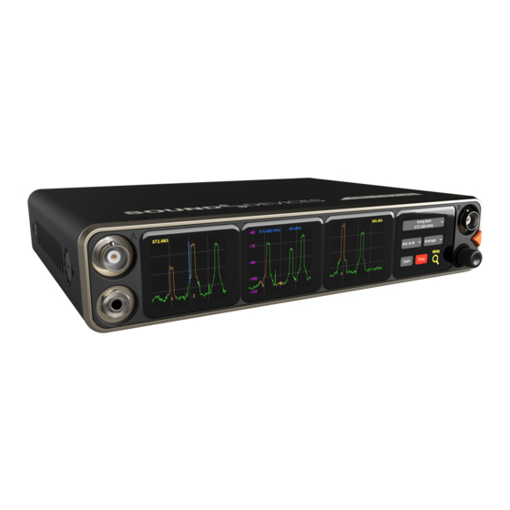
8-, 12-, and 16-channel, true-diversity receiver with spectraband technology
Hide thumbs
Also See for A20-Nexus:
- User manual (113 pages) ,
- Quick start manual (5 pages) ,
- User manual (87 pages)

Related Manuals for Sound Devices A20-Nexus


Summary of Contents for Sound Devices A20-Nexus
- Page 1 A20-Nexus 8-, 12-, and 16-Channel, True-Diversity Receiver with SpectraBand Technology User Guide v1.00...
-
Page 2: Table Of Contents
Digital Wireless Modulation NexLink Wireless Transmitter Control GainForward Architectural Overview Panel Views Typical Setups Quick Start Powering Navigating the A20-Nexus User Interface Menus RTSA (Real Time Spectrum Analyzer) Scan Mode TX List RF Menu Antenna RF Overload Indication Audio Outputs... - Page 3 A20-Nexus Specifications A20-Monarch Specifications Note on RF Interference Servicing the A20-Nexus Warranty Legal Notices Declaration of Conformity A20-Nexus User Guide...
-
Page 4: Welcome To The A20-Nexus
RF link. The A20-Nexus can be mounted in a standard 19-inch rack or easily placed remotely near the microphone transmitters due to its ability to be powered by Power-over-Ethernet (PoE+), its Dante audio-over-IP, and built-in web server for control via phone, tablet, or computer. -
Page 5: Spectraband
Audio levels from the transmitter are controlled either directly from the 8-Series (or any other mixer) trim controls, or from the A20-Nexus receiver screen. If the talent speaks too softly or emotes too loudly after being... - Page 6 When the A20-Nexus is docked on an 8-Series, the Nexus’s gain, low cut, and polarity settings are bypassed and hidden. In this case, adjust the 8-Series’ trim, low cut and polarity gain as necessary. See the 8-Series User Guides for more information.
-
Page 7: Architectural Overview
24 MHz of IF energy into a digital version of that signal. The real magic of the entire A20-Nexus happens within the Field-Programmable Gate Array (FPGA). An FPGA is essentially a giant custom, massively-parallel processor programmed in house. -
Page 8: Panel Views
Red when headphone output is clipping. ● Flashing orange when selected Sync Reference is not detected. ● Solid green when the front panel is locked out. See menu (Main Menu>System>Lockout Mode). 7: Headphone Output 3.5 mm connector A20-Nexus User Guide... - Page 9 Dual SMA-F ports for connecting 2.4 GHz SMA-M antennas for NexLink. Both antennas need to be connected. Important: Only use the 2.4 GHz SMA-M antennas supplied with the A20-Nexus or equivalent. Do not use 2.4 GHz RP-SMA antennas such as those used for the 8-Series bluetooth antenna.
- Page 10 2: Expansion Port For docking A20-Nexus to an 8-Series mixer/recorder using the A20-QuickDock optional accessory. The expansion port provides power from the 8-Series and passes the multichannel receiver digital audio signals from A20-Nexus to the 8-Series. When docked on an 8-Series: ●...
- Page 11 ● A20-Nexus rear panel connectors are disabled apart from the antenna connectors, control network, and the USB-A port. ● The USB-A port has the following capabilities: ○ Pairing A20-Mini transmitters to the A20-Nexus by connecting a USB-C cable from the transmitter to the USB-A port.
-
Page 12: Typical Setups
Typical Setups The versatile A20-Nexus can be used in many types of setup and workflow. This section details just a few examples. 1. Bag Setup: Nexus docked to an 8-Series Mixer-Recorder The A20-QuickDock accessory enables the A20-Nexus to be docked to an 8-Series mixer-recorder. The bottom panel incorporates a multi-pin expansion port that connects power from the 8-Series and passes the multichannel receiver digital audio from A20-Nexus to the 8-Series. - Page 13 Remotely locating the A20-Nexus multichannel receiver close to talent significantly reduces the chance of RF dropouts since the distance between those wearing the transmitters and the A20-Nexus receiver is minimized. A single CAT cable can be used to transport Dante audio and remote control data between Nexus and the sound mixer. As well as sending Dante audio to the mixer, the Nexus can also receive Dante audio back from the mixer, useful for distributing VoG and/or IFB feeds etc via its analog D-Sub outputs.
- Page 14 3. Remote Setup: Nexus located on set, close to talent, powered from PoE+ Similar to the previous setup, but with the Nexus being powered over PoE+. In this example, a computer is controlling Nexus via the Web App and is also sending and receiving Dante to and from Nexus. A20-Nexus User Guide...
- Page 15 A typical cart setup with Nexus. As well as sending Dante audio to the mixer, the Nexus can also send audio from its AES or Analog D-Sub outputs. In this example, the Nexus Web App is running on a tablet and controlling the Nexus over Wi-Fi. A20-Nexus User Guide...
-
Page 16: Quick Start
Ensure Country is set to the country that you are in. The Country setting determines which Tuning Bands and RF frequencies are legally unrestricted and available for selection in the A20-Nexus. If using A20-Mini transmitters, make sure that the A20-Remote app they are paired to is also set to the same country. - Page 17 To pair an A20-Mini transmitter, ensure it has a charged battery or batteries installed, then connect its USB-C port to the A20-Nexus USB-A port. The A20 transmitter will appear in the TX List after a few seconds. The A20-Nexus will then automatically establish a NexLink connection between the transmitter and the next available receiver channel.
- Page 18 HP knob to bring up the gain until you see audio signal from the lav connected to the A20-Mini. Press the HP knob to store the gain value. 20. Put your headphones on and listen. Rotate the HP knob clockwise to increase the HP gain. Congratulations! You have your first wireless channel ready to go. A20-Nexus User Guide...
-
Page 19: Powering
Where possible, power via TA-4 or the 8-Series. While PoE is a practical and convenient option for powering the ● A20-Nexus remotely, it is slightly less efficient than straight DC. This is due to the finite efficiency of the PoE injector and the internal PoE supply of the Nexus. - Page 20 Power Outputs DC Out 1 and DC Out 2 When operated standalone and powered via TA4 DC inputs or PoE+, the A20-Nexus can provide power to peripherals via the two 4-pin Hirose DC Outputs (500 mA max between both outputs) on the rear panel. Enable or disable each DC Output from the Power menu.
-
Page 21: Navigating The A20-Nexus User Interface
Navigating the A20-Nexus User Interface The A20-Nexus is operated from its front panel triangle button, headphone knob, and four touch screens or remotely via its web interface. Triangle Button ● Press to power up. Press and hold to power down. - Page 22 8RX View ● 4RX View ● 1RX View Upon power up, the A20-Nexus shows the last displayed RX View. 8RX View ● Displays 8 receiver channel strips, two per screen. ● Tap two neighboring screens simultaneously to display the 4RX View for those receiver channels. For example, tap screen 2 and 3 simultaneously to display the 4RX View for receiver channels 3-6.
- Page 23 1-4. ● Tap any receiver channel screen to display its 1RX View. ● Tap the RTSA icon at the bottom of screen 4 to display the RTSA in screen 4. A20-Nexus User Guide...
- Page 24 If NexLinked to an A20-Mini transmitter, the frequency is pushed to or pulled from the transmitter. See System > More > NexLink Tuning Mode. HPF: Indicates if the HPF is active either on the transmitter (if an A10-TX) or receiver channel (if an A20-Mini transmitter). A20-Nexus User Guide...
- Page 25 NexLink Icon: Indicates the quality of the received 2.4 GHz NexLink signal from the transmitter. If the transmitter is not connected via NexLink, the NexLink Q Meter is grayed out. Tap to display the NexLinked Transmitter List from which you can select an A20-Mini transmitter to NexLink to. A20-Nexus User Guide...
- Page 26 17. ID On/Off Buttons: Tap to identify the A20-Mini transmitter. Its LEDs will start flashing blue. 18. LEDs On/Off buttons: Tap to enable or disable the A20-Mini’s LEDs. 19. Gear Menu: Provides access to two pages of other settings plus NexLink status alerts. A20-Nexus User Guide...
- Page 27 A20-Mini has synced successfully to the Nexus. Displays ‘TC synced’ when successfully synced. Tap again to return to the TC Icon. Note: The A20-Mini will hold its synced timecode accurately for 4 hours after power down, then reset. A20-Nexus User Guide...
-
Page 28: Menus
Menus All the A20-Nexus settings are organized into menus which are accessed via the top level Main Menu. The triangle button cycles between the current RX view, Main Menu, and RTSA. Press the triangle button one or two times to display the Main Menu. -
Page 29: Rtsa (Real Time Spectrum Analyzer)
Access the expanded RTSA View by tapping the center of the single screen RTSA View or by tapping the RTSA icon in the Main Menu or bottom of screen 1 in other menus. ● Exit the expanded RTSA View by pressing the triangle button. A20-Nexus User Guide... - Page 30 Ant A+B: Highest of Ant A and Ant B. Ant A,B: Both Ant A and Ant B. Tuning Band: Sets the A20-Nexus’s Tuning Band and displays its trace across the first three screens. The Tuning Band can also be set from the RF Menu.
- Page 31 -130dBm, -10 to -130 dBm, -30 to -130 dBm, and -50 to -130 dBm 13. Trace: The real time trace of the received RF spectrum. 14. Restricted Frequency Band: Vertical gray region indicates unselectable restricted frequencies. RTSA showing restricted frequency band A20-Nexus User Guide...
-
Page 32: Scan Mode
Upper or Lower Band. Cancel the popup by pressing the triangle button. ● When a Tuning Band is selected, the RTSA mode is automatically selected for that Tuning Band. A20-Nexus User Guide... -
Page 33: Tx List
Enter the TX List by tapping the TX List icon in the Main Menu. Connect the A20-Mini transmitter’s USB-C port directly to the A20-Nexus USB-A port or via a USB hub. It is not necessary for the A20-Mini to be powered on or for it to have a battery installed. -
Page 34: Rf Menu
BNC can be set to Cascade Out, ideal for daisy chaining units. When daisy chaining A20-Nexus, it is recommended to use an external powered antenna to overcome the 3 dB splitting loss in the Nexus so that the receivers maintain excellent range. - Page 35 LFA Version Info: Displays system information about the Wisycom LFA- B-F1. ● Tuning Band: Sets the A20-Nexus’s Tuning Band and displays its trace across the rightmost screen. The Tuning Band can also be set from the RTSA. See RTSA and Architectural Overview for more information.
-
Page 36: Antenna Rf Overload Indication
Audio Outputs When standalone, the A20-Nexus delivers its multichannel receiver audio via analog, AES, and Dante outputs. It can also be set up to convert incoming Dante audio and output it as analog or AES. When docked to an 8-Series mixer/recorder, the Nexus’s multichannel receiver audio is output via the expansion port to the 8-Series and Nexus’s analog, AES, and Dante outputs are disabled. - Page 37 Routing A20-Nexus Receiver Audio or Dante Inputs to Analog or AES Outputs The A20-Nexus’s top and bottom D-Sub 25-pin connectors can be set to output receiver channel audio or incoming Dante audio as analog (line, -10, mic level) or AES signal. By default, the D-Sub outputs are set to output receiver channels.
- Page 38 8-Series. ● If the selected sync reference input is not detected, the A20-Nexus switches to its internal clock AND the HP encoder ring LED flashes orange to indicate that the selected sync reference is not present or invalid.
-
Page 39: Timecode
● An A20-Mini is also synced from the A20-Nexus by connecting its USB-C port to the A20-Nexus USB-A port while in the Timecode menu. When connected, the Timecode Menu displays a Sync A20 button at the bottom of screen 4. -
Page 40: Networking
Tip: Disable Ethernet and Dante when not in use to reduce power consumption. Port Configuration when A20-Nexus is docked to an 8-Series Dante is disabled when the A20-Nexus is docked to an 8-Series and all ports are set to Control. Dante Settings and Port Configuration settings are hidden. - Page 41 This can take a minute or two. A20-Nexus Name Tap to enter a unique name for the A20-Nexus. The A20-DX Name is used as the Dante Device name in a Dante network and the network device name in a Control network.
-
Page 42: System Menu
Lockout mode can be enabled locally or via the web app. When Lockout mode is enabled, the HP encoder ring LED is backlit green to indicate that the A20-Nexus is still on. To enable Lockout mode from the Nexus, tap the Lockout Mode button. The following popup is displayed: “Are you sure? - Page 43 Important ● The A20-Nexus and its paired A20-Mini transmitters must be set to the same country for the Nexus to successfully set the transmitter frequencies via NexLink. ● To set Country for the A20-Mini transmitters, use the A20-Remote app. Refer to the A20-Mini User Guide for more information.
- Page 44 System Menu Page 2 NextLink Tuning Mode Determines whether A20-Mini transmitter settings are pushed from the A20-Nexus to the A20-Mini or pulled from the A20-Mini to the A20-Nexus. ● Push to Transmitter ● Pull from Transmitter ● Manual (not pushed or pulled; must be set manually) Plugins Tap Plugins to display currently installed plugins and to install new plugins.
-
Page 45: Quick Setup Menu
Quick Setup Menu Quick Setup provides a way to save and load A20-Nexus settings. Settings are saved to internal memory slots 1-4 or to a USB thumb drive connected to the USB-A port. Save Setup ● All Nexus’s current settings are saved when saving a setup. - Page 46 Turn On when Power is Applied Time Zone Daylight Savings On/Off TX List > Global TX Settings: Power Off confirmation, Stop Confirmation Default Settings The Load Setup list also includes a ‘Default Settings’ option for restoring the A20-Nexus to default settings. A20-Nexus User Guide...
-
Page 47: Nexus Web App
Note: To ensure the web app functions correctly, use the latest version of your preferred browser. Chrome and Safari are recommended. Note: When using a Wi-Fi access point with the A20-Nexus, it is best practice to switch the Wi-Fi access point to 5.8 GHz so that the Wi-Fi doesn’t interfere with the 2.4 GHz NexLink. - Page 48 Timecode: Displays the timecode connected to the Nexus’s LTC/WCK BNC input. Web App 1RX View ● Duplicates the functionality of the A20-Nexus’s front panel 1RX View. See View. ● When docked to an 8-Series, the Gain, HPF, and Polarity settings are handled on the 8-Series and as such are disabled in the Nexus web app.
- Page 49 Web App RTSA View For the most part, the Web App’s RTSA duplicates the functionality of the A20-Nexus’s front panel RTSA. See RTSA. Frequency Marker: Tap or click anywhere just above the RTSA graph to display the Frequency Marker at any desired frequency.
-
Page 50: Updating Firmware
Download new Nexus firmware PRG file from the Sound Devices website. Copy the PRG file to the root of a USB thumb drive that has been formatted by the A20-Nexus. See System menu. Insert the USB thumb drive into the rear panel USB-A port. -
Page 51: Accessories
Four 1/16” allen screws for securing the mounting plate to the bottom of the A20-Nexus. ● Three long 2 mm and two short 2 mm allen mounting pillars for securing the rear of the A20-Nexus with mounting plate to the top of the 8-Series. - Page 52 Place the A20-Nexus upside down on a clean, flat surface. Position the QuickDock mounting plate on the bottom of the A20-Nexus Align the four mounting plate holes (1) with the screw holes on the bottom of the A20-Nexus. Secure the mounting plate.
- Page 53 Reattach the Quick Release mechanism. Squeeze both the rear red release levers and locate the quick release mechanism so that the multi-pin connector mates with the expansion port on the A20-Nexus. Firmly press down and ensure the quick release mechanism is flush with the surface of the mounting plate.
- Page 54 Start by hooking the Nexus mounting plate onto the two rear mounting pillars on the 8-Series. Next, squeeze both front red release levers together and press down firmly on top of the A20-Nexus. Once located in place, release the red levers.
- Page 55 To undock the A20-Nexus from the 8-Series, Slide the A20-Nexus’s front-right black latch off the 8-Series mounting pillar. Squeeze both the front red release levers and lift the A20-Nexus from the front. Slide out the A20-Nexus towards the rear of the 8-Series to unhook.
-
Page 56: A20-Monarch Antenna
Mounting an A20-Nexus to the shelf. Turn the shelf upside down then align the A20-Nexus front panel with the front edge of the shelf. The holes in the shelf tray allow the A20-Nexus to be positioned to the left, center, or right of the shelf. - Page 57 Adjust the position of the cable clamp so that it aligns with the side panel screw hole near the rear of the Nexus. Use the 2 mm allen key to tighten the cable clamp. Connect the SMA cable to the nearest rear panel 2.4 GHz SMA port. Repeat above procedure for the other side’s antenna bracket. A20-Nexus User Guide...
-
Page 58: Frequency Band Restrictions
The wireless system operator needs to be aware of local regulations and comply with all applicable laws regarding operation of wireless devices. In some restricted frequency bands, the operator will need to obtain an unlock code from Sound Devices to assign a restricted frequency to the transmitter. -
Page 59: Connector Pin Assignments
(Ch 1-8 AES Out) 14–Digital Out 4 signal (-) 15–Digital Out 3 signal (+) 16–Digital Out 3 Ground 17–Digital Out 2 signal (-) 18–Digital Out 1 signal (+) 19–Digital Out 1 Ground 20–Unused 21–Unused 22–Unused 23–Unused 24–Unused 25–Unused A20-Nexus User Guide... - Page 60 Pin 4 = positive volts 4-pin Hirose Pin 1 = ground 10-18V, 500 mA max between both (DC Out 1 & 2) Pin 4 = positive volts outputs (ie, 250 mA + 250 mA) USB-A Per USB-IF standard 5V, 500mA A20-Nexus User Guide...
-
Page 61: A20-Nexus Specifications
A20-Nexus Specifications Specifications are subject to change without prior notice. For the latest information available on all Sound Devices products, visit our website: www.sounddevices.com Patents: The A20-Nexus is protected by US patents US10678294B2, US20190166523A1, International patent WO2018022209A1, and several patents pending. - Page 62 -10 °C to +55 °C Dimensions (H x W x D) ● 4.0 cm x 20.3 cm x 16.7 cm ● (1.6 in x 8.0 in 6.6 in) Weight ● 1.27 kg (unpackaged) ● 2.8 lbs (unpackaged) A20-Nexus User Guide...
-
Page 63: A20-Monarch Specifications
Better than 15 dB across entire 470 - 1600 MHz range Mounting Threads ● ¼”-20 Dimensions (H x W x D) ● 17.0 cm x 21.0 cm x 1.7 cm ● (6.68 in x 8.26 in 0.67 in) Weight ● 0.12 kg (unpackaged) ● 0.26 lbs (unpackaged) A20-Nexus User Guide... -
Page 64: Note On Rf Interference
Note on RF Interference Sound Devices does not guarantee the absence of any interfering spurs across all bands in all situations. Some small spurs can originate within the Nexus, and others can come from many sources (Ethernet, AES/EBU interconnects, external mixer/recorders, USB drives, USB keyboards, etc.). -
Page 65: Legal Notices
Copyright© 2022 Sound Devices, LLC. All rights reserved. This product is subject to the terms and conditions of a software license agreement provided with the product, and may be used in accordance with the license agreement. This document is protected under copyright law. - Page 66 Changes or modifications not expressly approved by the manufacturer could void the user’s authority to operate the equipment. To comply with FCC part 15 rules in the United States, the A20-Nexus receiver must be professionally installed. It is the responsibility of the operator and professional installer to ensure that only certified antennas are to be used in the United States.
- Page 67 1) ce dispositif ne peut pas causer d’interférences, et 2) ce dispositif doit accepter toute interférence, y compris les interférences qui peuvent causer un mauvais fonctionnement de l’appareil. WEEE Statement If you wish to discard a Sound Devices product in Europe, contact Sound Devices (England) for further information. A20-Nexus User Guide...
-
Page 68: Declaration Of Conformity
Declaration of Conformity Manufacturer’s Name: Sound Devices, LLC Manufacturer’s Address: E7556 State Road 23 and 33 Reedsburg, WI 53959 USA We, Sound Devices LLC, declare under our sole responsibility that the product Product Name: A20-Nexus Model Number: A20-Nexus Description: Digital Wireless Receiver...
Need help?
Do you have a question about the A20-Nexus and is the answer not in the manual?
Questions and answers