
Related Manuals for Sound Devices A20-RX


Summary of Contents for Sound Devices A20-RX
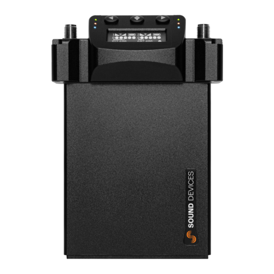
- Page 1 A20-RX Two-Channel, True Diversity Receiver with SpectraBand Technology User Guide v6.00...
-
Page 2: Table Of Contents
Table of Contents Welcome to the A20-RX SpectraBand Panel Views Basics of Navigating A20-RX Power Main Display A20-Mini GainForward Input Menu Selection Menu Operating the A20-RX Audio Output and Control SuperSlot User Groups Firmware Update Accessories and Adapters Antenna Guide... -
Page 3: Welcome To The A20-Rx
Welcome to the A20-RX Experience ultimate flexibility as you find available spectrum away from the crowded UHF TV band. The A20-RX two channel true diversity receiver features SpectraBand technology, which delivers a tuning range of 470 – 1525 MHz in a single unit – an industry first. -
Page 4: Spectraband
SpectraBand The A20-RX introduces SpectraBand, a technology that enables the A20-RX to tune over a super wide range of 470-1525 MHz. Tuning within this range varies by country. For instance: In the USA, the available frequency ranges are: ● The entire UHF TV band (470-608 MHz) ●... -
Page 5: Panel Views
Enters the menu selection. Also used to select options in the menu. 6: Right Button Moves the menu selection to the right, or increments values. 7: Display The screen can be set to turn off after a period of inactivity from the Selection menu (Main >Settings>Display>Screensaver). A20-RX User Guide... - Page 6 Used to secure various backplate accessories to the A20-RX. 2: Multi-Pin Accessory Connector Allows connection to various accessories and adapters. A20-RX either includes the A-SL, A-XLR, or A-TA3 (coming soon), depending on the model purchased. See Accessories and Adapters for detail...
-
Page 7: Basics Of Navigating A20-Rx
User Guide. The A20-RX displays the Dual Channel screen when powered on. Channel 1 status is displayed on the left and Channel 2 on the right. Press the Left button to navigate through Channel 1 related screens. Press the Right button to navigate Channel 2 related screens. -
Page 8: Power
Channel Power Each of the two channels of the A20-RX can be powered on or off individually. When a channel is powered down that portion of the A20-RX no longer draws power. When using A20-RX for a single wireless channel, best practice is to power down the unused channel. - Page 9 To quickly power channel 2 on and off, press and hold the Right and Center button for two seconds. Standby Mode The A20-RX enters Standby mode when the receiver is powered and both channels are powered off. Pressing any button displays the following.
-
Page 10: Main Display
Q-meter will display five bars. 9: RSSI Meter Receive Strength Signal Indicators (RSSI) are displayed on the screen. The bars indicate RF signal strength at each antenna for the selected frequency. A20-RX User Guide... - Page 11 When the channel is paired with an A10-TX, pressing the Left or Right button again shows the A10-TX Information screen. When the channel is paired with an A20-Mini, pressing the Left or Right button enters the A20-RX Input menu. The Input Menu is not available when the A20-RX is connected to the 833, 888, or Scorpio via the SL-2 or SL-6.
- Page 12 RF Overload Indication When an RF signal is approaching overload on either channel, the A20-RX’s green LED is solid and its red LED flashes on both channels 1 and 2. When the RF input is overloading on a channel, only the red LED flashes for that channel. This is an indication that the quality of the signal is degrading.
-
Page 13: A20-Mini Gainforward Input Menu
From the A20-RX home screen, press the channel’s directional button twice to enter the Input menu. From the Input menu, press the middle button to select a sub-menu to adjust gain, low cut, or limiter of the incoming A20-Mini transmitted signal. -
Page 14: Selection Menu
Selection Menu The A20-RX receiver is controlled through its main Selection menu. Enter the menu by first selecting either the channel 1 receiver (Left button) or channel 2 receiver (Right button), then press the Center button. Once in the menu, the Left and Right buttons toggle among options, and the Center button makes the selection. - Page 15 Inverted Mode Choose the audio output type of the A20-RX. When the A20-RX-XLR is set to AES the channel 2 XLR connection is not used. This setting applies to both channels. Mode is not available when A20-RX is mounted via A-SL to SL-2 and 8-Series.
- Page 16 Use the ‘Other’ option if your location is not listed. Display Enters Display sub-menu. ● Brightness ● Screensaver ● Orientation ● Options ● Q-meter LEDs When set to On the LEDs remain illuminated. Off deactivates the LEDs. ● ● A20-RX User Guide...
- Page 17 120 sec Orientation Sets the operating orientation of A20-RX in relation to the buttons, screen, and LEDs. The A20-RX can be used in an orientation with the buttons below the screen (normal), or with the buttons to the top (flipped).
- Page 18 Restore The restore function resets the A20-RX to the factory default settings. Restore sets Country to Other. Select the current Country in your locality before proceeding. ● Cancel ● Restore Info Shows information about the A20-RX ● Serial Number ●...
-
Page 19: Operating The A20-Rx
Compared to Standard Modulation, Long Range Modulation has better sensitivity. This increased sensitivity results in better range in challenging RF environments. The Modulation setting must match between the A20-Mini or A10-TX and the A20-RX in order for the transmitted signal to be received. - Page 20 TV Channel Frequency Preset, an asterisk character (*) is shown in the display adjacent to TV channel/sub channel assignment. TV Ch is not displayed or accessible throughout the A20-RX user interface when Band falls outside of the UHF band (470-694 MHz, country dependent).
- Page 21 No - frequency and band remains unchanged and returns to the scan results. Frequency AutoAssign AutoAssign scans the current tuning band and selects available frequencies for the A20-RX’s two channels. This feature is designed to make frequency selection quick and easy. There are two ways to AutoAssign frequencies: AutoAssign without a prior scan.
- Page 22 SMA connectors. Ensure that the antennae used are built for the correct frequency. See Antenna Guide for more details. For best operation and reception with the included 1/4-wave antenna, keep it in the free field, away from metal objects or transmitting devices. A20-RX User Guide...
-
Page 23: Audio Output And Control
When set to AES output in the Selection Menu the A20-RX outputs two-channel AES3 at 24-bit, 44.1 kHz. Channel 1 output appears at AES left, channel 2 appears at AES right. With the A20-RX-XLR the channel 1 XLR connector is used for AES3 output. The channel 2 XLR connector is not active when set to AES output... - Page 24 The wireless system operator needs to be aware of local regulations and comply with all applicable laws regarding operation of wireless devices. In some restricted frequency bands, the operator will need to obtain an unlock code from Sound Devices to assign a restricted frequency to the transmitter.
-
Page 25: User Groups
(U2, U3, etc). Each user in a group can be give a name and frequency, which after upload, will then be displayed on A10 receivers and transmitters. Each group can have up to 32 users. When the User Group .ALUG file is intended for use on the A20-RX, ensure that all user frequencies fall within the same A20-RX tuning band. - Page 26 Sending and Loading User Groups onto A20-RX While each User Group file may contain up to eight user groups, only one group at a time may be sent to and loaded on an A20-RX. A user group is sent to the A20-RX-XLR by directly connecting it to a computer via USB. Sending a user group to the A20-RX-SL is achieved via the A10-RACK or the Sound Devices 8-Series Mixer-Recorders with attached SL-2 or SL-6.
- Page 27 While the SD card can have multiple .ALUG files, each with up to eight groups, only one user group at a time may be loaded to a receiver. A20-RX receivers can operate in one of two modes: User and Factory. In Factory mode, frequencies are manually dialed in, but in User mode (when a user group is loaded), pre-set frequencies are dialed in by user name.
-
Page 28: Firmware Update
Connect the A20-RX via USB to the computer. The A-XLR, A-TA3, A-RXMON connect via Micro-USB. The A-15PIN connects via USB-C. Note: A USB 3.0 port is required to power the A20-RX via the A-15PIN. If a USB 3.0 port is not available, connect two USB 2.0 ports to the A-15PIN using the Sound Devices MX-USB Y USB-C to two USB-A Y-Cable. - Page 29 Select Update Firmware. Confirm the selected file when prompted and select OK to continue. As the receiver is updated, its screen will display Programming and the LEDs will turn off. Repeat steps for each receiver in the SL-2 or SL-6. A20-RX User Guide...
-
Page 30: Accessories And Adapters
Cradle for A20-RX with 15pin D-type adapter. For use with Sony camcorders that have slot-in for wireless, or Sony extension units with slot-in for wireless. The A-15PIN allows the A20-RX to be used in the Sony slot without the need for external cables. The audio is passed through the internal slot as a 2 channel AES input. - Page 31 Remove the attached accessory. Position the new accessory making connection to the A20-RX’s Multi-Pin Accessory connector, then replace the screws removed in step 1. A20-RX-SL DB-25 Connector Pin Assignments The illustration below shows the pin assignments of the A20-RX-SL when viewing the bottom connector.
- Page 32 Ch 2 - analog audio out, +2 dBu level (+/- 0.5 dB), balanced. no connection no connection no connection no connection no connection UART transmit UART from A20-RX. 0/3.3V signaling. (0/3.3V) UART receive UART to A20-RX. 0/3.3 V signaling. (0/3.3V) A20-RX User Guide...
- Page 33 Ground Ground connection A20-RX User Guide...
- Page 34 A20-RX-XLR A-XLR Connector Pin Assignments The illustration below shows the pin assignments of the A20-RX-XLR when viewing the break-out connectors. Connector Pins Name Description XLR Output 1 Ground Ground connection Ch 1+ analog / Ch 1 + analog audio out, +2 Ch 1,2 AES + dBu level (+/- 0.5 dB),...
- Page 35 Hirose In. A20-RX-TA3 A-TA3 Connector Pin Assignments The illustration below shows the pin assignments of the A20-RX-TA3 when viewing the bottom connectors. Connector Pins Name Connection TA3 Output 1 Ground Ground connection Ch 1+ analog / Ch 1 + analog audio out, +2 Ch 1,2 AES + dBu level (+/- 0.5 dB),...
- Page 36 USB-C, power needs to be applied to the TA-4 or Hirose. A20-RX User Guide...
- Page 37 A20-RX Specifications Specifications are subject to change without prior notice. For the latest information available on all Sound Devices products, visit our website: www.sounddevices.com RF Tuning ● 470 to 1525 MHz ● SpectraBand Technology ● Transmitters tunable in 25 kHz steps ●...
-
Page 38: Antenna Guide
2 uncut antennas (1 straight, 1 right-angle) ● 6 antenna caps Sound Devices offers additional pre-cut and uncut antennas as available options. Attach antennas with a length specific to the frequency in use. Using the wrong length of antenna reduces RF range. Cutting Antennas to Length Uncut antennas need to be cut to the length specific to the frequency for intended use. -
Page 39: Servicing The A20-Rx
Servicing the A20-RX Do not attempt to service the A20-RX. The internal parts are microscopic and not user serviceable. Please send to Sound Devices for any service needs. https://service.sounddevices.com/contact-support/ Warranty Sound Devices, LLC warrants the items listed above against defects in materials and workmanship for a period of ONE (1) year from date of original retail purchase. -
Page 40: Legal Notices
Copyright© 2022 Sound Devices, LLC. All rights reserved. This product is subject to the terms and conditions of a software license agreement provided with the product, and may be used in accordance with the license agreement. This document is protected under copyright law. - Page 41 (2) l’utilisateur de l’appareil doit accepter tout brouillage radioélectrique subi, même si le brouillage est susceptible d’en compromettre le fonctionnement. . WEEE Statement If you wish to discard a Sound Devices product in Europe, contact Sound Devices (England) for further information. A20-RX User Guide...
- Page 42 A20-RX User Guide...
- Page 43 Post Office Box 576 E7556 State Rd. 23 and 33 Reedsburg, Wisconsin 53959 USA support@sounddevices.com +1608.524.0625 main 800.505.0625 toll free (U.S. only) www.sounddevices.com A20-RX User Guide...
Need help?
Do you have a question about the A20-RX and is the answer not in the manual?
Questions and answers