Mercoid MPC Series Specifications-Installation And Operating Instructions
Pump controller
Hide thumbs
Also See for MPC Series:
- Installation and operating manual (32 pages) ,
- Installation and operating manual (32 pages)
Table of Contents
Advertisement
Quick Links
1.800.561.8187
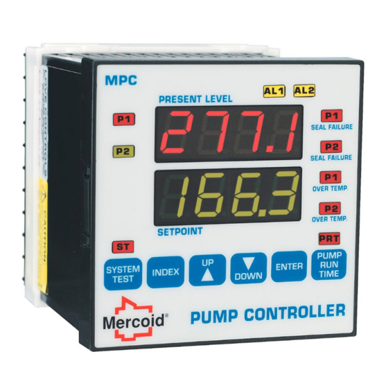
Series MPC Pump Controller
Specifications - Installation and Operating Instructions
TABLE OF CONTENTS
Dimensions . . . . . . . . . . . . . . . . . . . . . . . . . . . . . . . .1
Specifications . . . . . . . . . . . . . . . . . . . . . . . . . . . . . .1
Getting Started . . . . . . . . . . . . . . . . . . . . . . . . . . . . . .2
Model Identification . . . . . . . . . . . . . . . . . . . . . . . . . .2
Installation . . . . . . . . . . . . . . . . . . . . . . . . . . . . . . . . .2
Wiring . . . . . . . . . . . . . . . . . . . . . . . . . . . . . . . . . . . 3-5
Front Panel Functions . . . . . . . . . . . . . . . . . . . . . . 6-7
Home Display . . . . . . . . . . . . . . . . . . . . . . . . . . . . . . .7
Security Level Selection . . . . . . . . . . . . . . . . . . . . . .7
Lead/Lag Operation . . . . . . . . . . . . . . . . . . . . . . . . . .7
Seal Failure Operation . . . . . . . . . . . . . . . . . . . . . 7-8
Over Temperature Operation . . . . . . . . . . . . . . . . . .8
Analog Retransmission Operation . . . . . . . . . . . . .8
Pump Run Time Operation . . . . . . . . . . . . . . . . . . . .8
Serial Communication Operation . . . . . . . . . . . . . . .8
Menu Selections . . . . . . . . . . . . . . . . . . . . . . . . . . . .9
Secondary Menu . . . . . . . . . . . . . . . . . . . . . . . . . . . .9
Secure Menu . . . . . . . . . . . . . . . . . . . . . . . . . . . 10-11
Alarm Type and Action . . . . . . . . . . . . . . . . . . . 11-12
Diagnostic Error Messages . . . . . . . . . . . . . . . . . .13
Programming Chart . . . . . . . . . . . . . . . . . . . . . . . . .14
Programming Example . . . . . . . . . . . . . . . . . . . . . .15
www.
4-1/2 [114.3]
17/32 [13.5]
3-19/32
[91.3]
PANEL CUT-OUT: 3.620 X 3.620 IN, +0.032/-0.000
[92 X 92 MM, +0.8/-0.0].
ALLOW FOR 0.5 IN [13 MM] CLEARANCE
AT THE REAR OF THE INSTRUMENT.
SPECIFICATIONS
Inputs: 4-20 mA DC or 2.0 to 10.0 V DC selectable.
Input Impedance: Current input: 10 Ω, Voltage input:
100K Ω.
Output Ratings: Control relays: SPDT, rated 10A @
240 VAC res., 1/4 hp @120 VAC, 1/3 hp @ 240 VAC;
Alarm relays: SPST, 3A @ 240 VAC res., 1/10 hp @
120 VAC.
Control Type: On/off, reverse or direct acting.
Power Requirements: 100-240 VAC nominal,
+10%-15%, 50 to 400 Hz, single phase; 132-240 VDC
nominal, +10%-15%.
Power Consumption: 7.5 VA max.
Accuracy: 0.25% of span, 1 least significant digit.
Display: Two 4 digit, 7 segment 0.56˝ high LEDs.
Display Resolution: 1 count.
Memory Backup: Nonvolatile memory (no batteries
required).
Serial Communications: Optional RS-232 or RS-485
with Modbus
protocol.
®
Ambient Operating Temperature / RH: 14 to
131°F (-10 to 55°C) / 0 to 90% up to 104°F (40°C)
non-condensing, 10 to 50% at 131° F (55°C) non-
condensing.
Weight: 16 oz. (454 g).
Front Panel Rating: Meets UL type 4X (IP66).
Loop Power Supply (Isolated): 24 VDC @ 50 mA,
regulated.
Seal Failure (Moisture Sensor): Power supply
to moisture sensor: 2.5 VDC; Search current: 3
micro amps; Resistance sensitivity: 10K to 500K Ω;
Resistance resolution: 10K Ω steps.
Over Temperature: Input: Dry contact on transistor
switch (NPN open collector type); Current: 1 mADC;
Isolation: Shares common ground with transmitter
input.
Alarm On-Off Differential: 1 count.
Set Point Range: Selectable.
Power Voltage Stability: 0.05% over the power
voltage range.
Temperature Stability: 100 PPM/°C typical, 200
PPM/°C maximum.
Common Mode Rejection: 140 db minimum at 60
Hz.
Normal Mode Rejection: 65 db typical, 60 db at 60
Hz.
Isolation: Relay: 1500 VAC to all other inputs and
outputs; 24 VDC loop power: 500 VAC to other inputs
and outputs; Process output: 500 VAC to other inputs
and outputs; Seal failure input: 500 VAC to other
inputs and outputs.
Storage Temperature: -40 to 176° F (-40 to 80° C).
Agency Approvals: UL 508.
1
.com
Bulletin L-20
3-25/32 [95.9]
3-25/32
[95.9]
MEETS IP66 [UL TYPE 4X]
MAX. PANEL
THICKNESS 0.25 [6.35]
information@itm.com
Advertisement
Table of Contents

Related Manuals for Mercoid MPC Series


Summary of Contents for Mercoid MPC Series
-
Page 1: Table Of Contents
Bulletin L-20 Series MPC Pump Controller Specifications - Installation and Operating Instructions 4-1/2 [114.3] 17/32 [13.5] 3-25/32 [95.9] 3-19/32 3-25/32 [91.3] [95.9] PANEL CUT-OUT: 3.620 X 3.620 IN, +0.032/-0.000 MEETS IP66 [UL TYPE 4X] [92 X 92 MM, +0.8/-0.0]. MAX. PANEL ALLOW FOR 0.5 IN [13 MM] CLEARANCE THICKNESS 0.25 [6.35] AT THE REAR OF THE INSTRUMENT. -
Page 2: Getting Started
GETTING STARTED 1. Install the control as described on page 2. 2. Wire the control following the instructions on pages Panel cut-out: 3 through 5. Page 3 contains basic wiring for the 3.620 x 3.620 in, control. If using the Series MPC’s transmitter power +0.032/-0.000 supply follow the additional directions on page (92 x 92 mm,... -
Page 3: Wiring
WIRING Do not run transmitter wiring or other class 2 wiring in the same conduit as power leads. Use only the probe or transmitter for which the control has been programmed. Maintain separation between wiring of sensor, auxiliary in or out, and other wiring. See the ˝Secure Menu˝ for input selection. - Page 4 WIRING FOR TRANSMITTER INPUTS USING INTEGRAL POWER SUPPLY Wire power and outputs as shown on previous page. Wiring for two-wire transmitters shown below in Figure 3. All wiring shown in Figure 3 is Class 2. CONNECT JUMPER BETWEEN TERMINALS 2 AND 12 CONNECT TRANSMITTER PLUS [+] TO TERMINAL 11 22 23 24 25 26...
- Page 5 WIRING FOR 485 AND 232 SERIAL COMMUNICATION OPTIONS Wire power and outputs as shown on page 3. Wiring for options is shown in Figure 4 below. All wiring shown below is Class 2. Shielded twisted pair is recommended for Option 485. DO NOT run signal wiring in the WARNING same conduit or chase as the power...
-
Page 6: Front Panel Functions
FRONT PANEL FUNCTIONS ALARM LAMPS PUMP 1 SEAL PUMP 1 FAILURE LAMP ON LAMP PUMP 2 PUMP 2 SEAL ON LAMP FAILURE LAMP PUMP 1 OVER LEVEL TEMPERATURE DISPLAY LAMP 1ST SET POINT PUMP 2 OVER DISPLAY TEMPERATURE LAMP SYSTEM PUMP RUN TEST TIME LAMP... -
Page 7: Home Display
LEAD/LAG OPERATION INDEX AND DOWN ARROW: Pressing these The Mercoid MPC pump controller is designed to easily ® keys simultaneously will allow backing up one operate a pair of pumps in the most efficient manner menu item, or if at the first menu item they will possible. -
Page 8: Over Temperature Operation
The thermostat has a preset value from the pump OPERATION manufacturer at which point the pump needs to be shut The serial communications options allow the control to down. The Mercoid MPC detects when the thermostat ® be written to and read from a remote computer or other signal changes to open and shuts down the pump. -
Page 9: Menu Selections
MENU SELECTIONS Pump 1 Run Time: Total ON Time for Pump 1 in P1rn Notation Conventions for the Menus HOURS since last reset (0000 - 9999 hours). Because of the number of features available in this control, information is included that may not apply to your Pump 2 Run Time: Total ON Time for Pump 2 in P2rn specific control. -
Page 10: Secure Menu
Secure Menu 0SUP Zero Suppression: Select 0n or 0FF. Factory default Press the INDEX key for 5 seconds to start the menu. is 0n. Press INDEX to advance to the next menu item. 0FF The input range will start at 0 (zero) Input. Press UP ARROW or DOWN ARROW to change... -
Page 11: Alarm Type And Action
PrSt Pump Run Time Reset: Select 0n or 0FF. Selecting IF INHIBIT IS ON AND A POWER WARNING 0n will allow Pump Run Time to be reset in the FAILURE OCCURS DURING A Secondary menu while an 0FF selection will not HIGH ALARM, RESTORATION OF POWER WILL NOT allow Pump Run Time to be reset. - Page 12 A1td Alarm 1 Time Delay: Select 0FF or 1 to 8000 Fi L t Digital Filter: Select 0FF or 1 to 99. In some cases seconds. Factory default is 0FF. the time constant of the sensor, or noise could Alarm function will operate when triggered at cause the display to jump enough to be unreadable.
-
Page 13: Diagnostic Error Messages
DIAGNOSTIC ERROR MESSAGES Display Meaning SP Outputs Action Required No display Display is blank. Instrument is Set point Check that the power supply is on, or that the lighted not getting power, or the supply outputs inactive external fuses are good. voltage is too low. -
Page 14: Programming Chart
PROGRAMMING CHART Use the charts on this and the next page to record the values in your application. You may want to photocopy the pages if you plan to make programming changes. Menu Item Default Set At Description Primary Home Position, Process Variable and SP1H’s Value displayed PV SP1H Secondary SP1H Set Point 1 value (default is in feet) -
Page 15: Programming Example
PROGRAMMING EXAMPLE Example: • Keep Empty, two pump (duplex) • Depth 25 feet • Pump 1: Start at 6 feet Stop at 3 feet Pump 2: Start at 12 feet Stop at 9 feet • Low level alarm: 1 foot, fixed, auto reset HIGH LEVEL ALARM •... - Page 16 NOTES __________________________________________________________________________________________________________________________________________ __________________________________________________________________________________________________________________________________________ __________________________________________________________________________________________________________________________________________ __________________________________________________________________________________________________________________________________________ __________________________________________________________________________________________________________________________________________ __________________________________________________________________________________________________________________________________________ __________________________________________________________________________________________________________________________________________ __________________________________________________________________________________________________________________________________________ __________________________________________________________________________________________________________________________________________ __________________________________________________________________________________________________________________________________________ __________________________________________________________________________________________________________________________________________ __________________________________________________________________________________________________________________________________________ __________________________________________________________________________________________________________________________________________ __________________________________________________________________________________________________________________________________________ __________________________________________________________________________________________________________________________________________ __________________________________________________________________________________________________________________________________________ __________________________________________________________________________________________________________________________________________ __________________________________________________________________________________________________________________________________________ __________________________________________________________________________________________________________________________________________ __________________________________________________________________________________________________________________________________________ __________________________________________________________________________________________________________________________________________ __________________________________________________________________________________________________________________________________________ __________________________________________________________________________________________________________________________________________ __________________________________________________________________________________________________________________________________________ __________________________________________________________________________________________________________________________________________ __________________________________________________________________________________________________________________________________________ __________________________________________________________________________________________________________________________________________ __________________________________________________________________________________________________________________________________________ __________________________________________________________________________________________________________________________________________ __________________________________________________________________________________________________________________________________________ Modbus is a registered trademark of Schneider Automation, Inc. ®...
Need help?
Do you have a question about the MPC Series and is the answer not in the manual?
Questions and answers