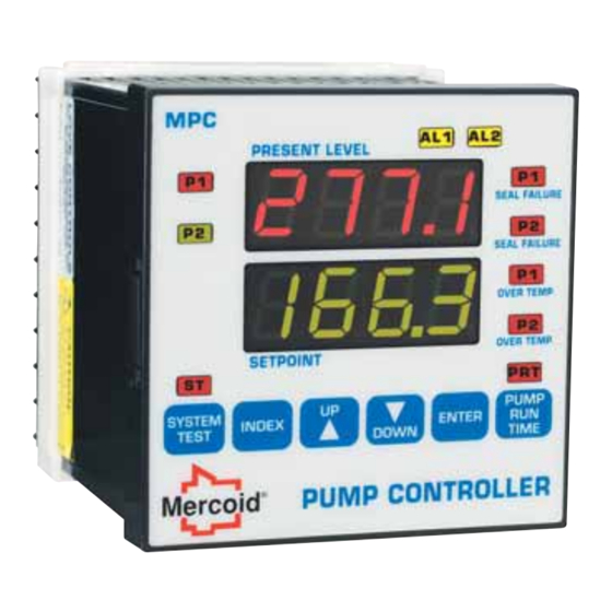
Mercoid Series MPC Installation And Operating Manual
Pump controller
Hide thumbs
Also See for Series MPC:
- Installation and operating manual (32 pages) ,
- Specifications-installation and operating instructions (16 pages)
Table of Contents
Advertisement
Advertisement
Table of Contents

Related Manuals for Mercoid Series MPC


Summary of Contents for Mercoid Series MPC
- Page 1 Bulletin L-20 Series MPC Pump Controller Installation and Operating Manual MERCOID A Division of Dwyer Instruments, Inc. P.O. BOX 258 • MICHIGAN CITY, INDIANA 46361, U.S.A. Phone: 219/879-8000 • Fax: 219/872-9057 www.dwyer-inst.com • e-mail: lit@dwyer-inst.com FR # MI-443247-00 Rev. 3...
-
Page 2: Table Of Contents
CONTENTS Dimensions ............. 1 Specifications . -
Page 3: Specifications
SPECIFICATIONS Inputs: 4 to 20 mA DC or 2.0 to 10.0 V DC selectable. Input Impedance: Current input: 10 ohms, Voltage input: 100K ohms. Output Ratings: Control Relays: SPDT, rated 10A @ 240 VAC res., 1/4 hp @120 VAC, 1/3 hp @ 240 VAC. Alarm Relays: SPST, 3A @ 240 VAC res., 1/10 hp @ 120 VAC. -
Page 4: Getting Started
2. Wire the control following the instructions on pages 5 through 7. Page 5 contains basic wiring for the control. If using the Series MPC’s transmitter power supply follow the additional directions on page 6. Wiring instructions for the 232 and 485 series communication options is included on page 7. -
Page 5: Installation
INSTALLATION Mount the instrument in a location that will not be subject to excessive temperature, shock, or vibration (see Specifications for specific tolerances). All models are designed for mounting in an enclosed panel. Select the position desired for the instrument on the panel. Prepare the panel by cutting and deburring the required opening. -
Page 6: Wiring
WIRING Do not run transmitter wiring or other class 2 wiring in the same conduit as power leads. Use only the probe or transmitter for which the control has been programmed. Maintain separation between wiring of sensor, auxiliary in or out, and other wiring. See the ˝Secure Menu˝... - Page 7 WIRING FOR TRANSMITTER INPUTS USING INTEGRAL POWER SUPPLY Wire power and outputs as shown on previous page. Wiring for two-wire transmitters shown below in Figure 3. All wiring shown in Figure 3 is Class 2. Figure 3 - Transmitter Wiring Connect Jumper between terminals 2 and 12 Connect Transmitter Plus (+) to terminal 11 Connect Transmitter...
-
Page 8: Wiring
WIRING FOR 485 AND 232 SERIAL COMMUNICATION OPTIONS Wire power and outputs as shown on page 5. Wiring for options is shown in Figure 4 below. All wiring shown below is Class 2. Shielded twisted pair is recommended for Option 485. DO NOT run signal wiring in the same conduit or chase as the power wiring. -
Page 9: Front Panel Functions
FRONT PANEL FUNCTIONS Key functions are as follows: INDEX: Pressing the INDEX key for 2 seconds will bring up the Secondary menu starting at the SP1H menu item. Holding the key for 5 seconds will bring up the Secure menu starting with the menu item SECr . -
Page 10: Home Display
INDEX & DOWN ARROW: Pressing these keys simultaneously will allow backing up one menu item, or if at the first menu item they will cause the display to return to the primary menu. If an alarm condition has occurred, these keys may be used to reset the alarm. INDEX &... -
Page 11: Security Level Selection
SECURITY LEVEL SELECTION Three levels of security are provided. The SECr menu item security level may be viewed or changed at any time regardless of the present security level in the Secure menu. The display shows the current security level. To change security levels change the password value using the UP ARROW or DOWN ARROW keys and pressing the... -
Page 12: Lead/Lag Operation
LEAD/LAG OPERATION The Mercoid ® MPC pump controller is designed to easily operate a pair of pumps in the most efficient manner possible. The controller has a 'lead/lag' feature that allows two pumps to operate in an alternating fashion to minimize wear. -
Page 13: Over Temperature Operation
Most pumps have an installed normally closed thermostat for over temperature protection of the pump. The thermostat has a preset value from the pump manufacturer at which point the pump needs to be shut down. The Mercoid ® MPC detects when the thermostat signal changes to open and shuts down the pump. -
Page 14: Analog Retransmission Operation
ANALOG RETRANSMISSION OPERATION The analog retransmission allows the Process Variable to be sent as an analog signal to an external device. The signal may be either 2 to 10 VDC (option RV) or 4 to 20 mADC (standard). The output may be changed in the field from one to the other by the toggle switch located on the top printed circuit board, factory standard is mADC. -
Page 15: Serial Communication Operation
OPTION 232, 485 SERIAL COMMUNICATION OPERATION The serial communications options allow the control to be written to and read from a remote computer or other similar digital device. Communication is allowed either through a RS-485 (Option 485) port, or a RS-232 (Option 232) port. Wire the communication lines as shown on Page 7. -
Page 16: Menu Selections
MENU SELECTIONS Notation Conventions for the Menus Because of the number of features available in this control, information is included that may not apply to your specific control. All usable features are included in this book, but may not be used in your process. To increase clarity the following conventions are used: 1. - Page 17 P1rn Pump 1 Run Time: Total ON Time for Pump 1 in HOURS since last reset (0000 - 9999 hours). Pump 2 Run Time: Total ON Time for Pump 2 in HOURS since last reset P2rn (0000 - 9999 hours). P1SF Pump 1 Reset for Seal Failure.
-
Page 18: Secure Menu
Secure Menu Press the INDEX key for 5 Seconds to start the menu. Press INDEX to advance to the next menu item. Press UP ARROW or DOWN ARROW to change the value in the display. Press ENTER to retain the value. OUTPUTS ARE DISABLED (TURNED OFF) WHILE CONTROL IS IN THE SECURE MENU. - Page 19 0SUP Zero Suppression: Select . Factory default is The input range will start at 0 (zero) Input. The input range will start at 4.00 mA or 2.00 V. Input Type: Select one of the following. Refer to the Input wiring section for the proper wiring.
- Page 20 PrSt Pump Run Time Reset: Select . Selecting will allow Pump Run Time to be reset in the Secondary menu while an selection will not allow Pump Run Time to be reset. Set Point High: Select from the highest input range value to value.
-
Page 21: Alarm Type And Action
ALARM TYPE AND ACTION Caution: In any critical application where failure could cause expensive product loss or endanger personal safety, a redundant limit controller is required. When setting an alarm value for an absolute alarm ( simply set the value at which the alarm is to occur. When setting the alarm value for a deviation alarm ( ), set the difference in value from the Set Point (... - Page 22 High Alarm Only. A1Hi appears in the Secondary Menu. HiLo High and Low Alarms. Both A1Lo A1Hi appear in the Secondary Menu, and share the same Alarm 1 Relay output. Seal Failure ONLY will trigger Alarm. Over Temperature Failure ONLY will trigger Alarm SF0t Both Seal Failure and Over Temperature Failure will trigger Alarm.
- Page 23 Alarm 2 function: Select HiLo , or SF0t . Factory default is Alarm 2 is disabled. No Alarm 2 menu items appear in the Secondary or Secure menus. Low Alarm Only. appears in the Secondary Menu. A2Lo High Alarm Only. A2Hi appears in the Secondary Menu.
- Page 24 FiLt Digital Filter: Select . In some cases the time constant of the sensor, or noise could cause the display to jump enough to be unreadable. If this value is set too high, controllability will suffer. Factory default is (Analog Retransmission Output, see page 13) Process Output High: Select from any value greater than to 9999 counts.
-
Page 25: Diagnostic Error Messages
DIAGNOSTIC ERROR MESSAGES Display Meaning SP Outputs Action Required Display is blank. Set point Check that the power supply display Instrument is not outputs inactive is on, or that the external lighted getting power, or Alarms inactive fuses are good. the supply voltage is too low. -
Page 26: Diagnostic Error Messages
DIAGNOSTIC ERROR MESSAGES Display Meaning SP Outputs Action Required Underflow or Set point Input signals may normally Overflow: Process outputs active go above or below range value has Alarms active ends. If not, check input and exceeded input correct. range ends. CHEC Check calibration Set point... -
Page 27: Programming Chart
PROGRAMMING CHART Use the charts on this and the next page to record the values in your application. You may want to photocopy the pages if you plan to make programming changes. Menu Item Default Set At Description Primary PV SP1H XXXX Home Position, Process Variable &... - Page 28 Menu Item Default Set At Description AUtO Pump Seal Failure controller action (selectable automatic or manual reset) TESt System Test (Selectable on or off) PrSt Pump Run Time Rest (Selectable on or off) 23.1 Set Point High value (default is in feet) Set Point Low value (default is in feet) S1PI Set Point 1 Power Interrupt...
- Page 29 Menu Item Default Set At Description Process Output Low (default is in feet) LorE Local/Remote for computer communications Addr Control Address for computer Secure communications bAUd Baud Rate for computer communications No Activity Timer for computer communications Stor Store Menu for Hi speed writes (selectable yes or no)
-
Page 30: Programming Example
PROGRAMMING EXAMPLE Example: • Keep Empty, two pump (duplex) • Depth 25 feet • Pump 1: Start at 6 feet Stop at 3 feet Pump 2: Start at 12 feet Stop at 9 feet • Low level alarm: 1 foot, fixed, auto reset •... - Page 31 EXAMPLE PROGRAMMING CHART continued Menu Item Default Set At Description Security Selection Scale High value (default is in feet) Low value (default is in feet) Decimal Point Positioning Set Point 1 State (selectable POut (Pumping Out) or PIn (Pumping In)) Set Point 2 State (selectable POut (Pumping Out), PIn (Pumping In), or off) Lead/Lag (selectable on or off)
- Page 32 Digital Filter 23.1 Process Output High (default is in feet) Process Output Low (default is in feet) MERCOID A Division of Dwyer Instruments, Inc. P.O. BOX 258 • MICHIGAN CITY, INDIANA 46361, U.S.A. Phone: 219/879-8000 • Fax: 219/872-9057 www.dwyer-inst.com • e-mail: lit@dwyer-inst.com Copyright 2010 by Dwyer Instruments Inc.
Need help?
Do you have a question about the Series MPC and is the answer not in the manual?
Questions and answers