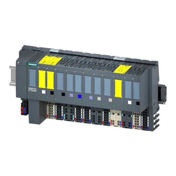
Siemens SIMATIC ET 200SP Manual
Digital input module di 8x24vdc ba
Hide thumbs
Also See for SIMATIC ET 200SP:
- System manual (409 pages) ,
- Manual (270 pages) ,
- Equipment manual (166 pages)
Table of Contents
Advertisement
Advertisement
Table of Contents


Need help?
Do you have a question about the SIMATIC ET 200SP and is the answer not in the manual?
Questions and answers