Advertisement
Technical Instructions
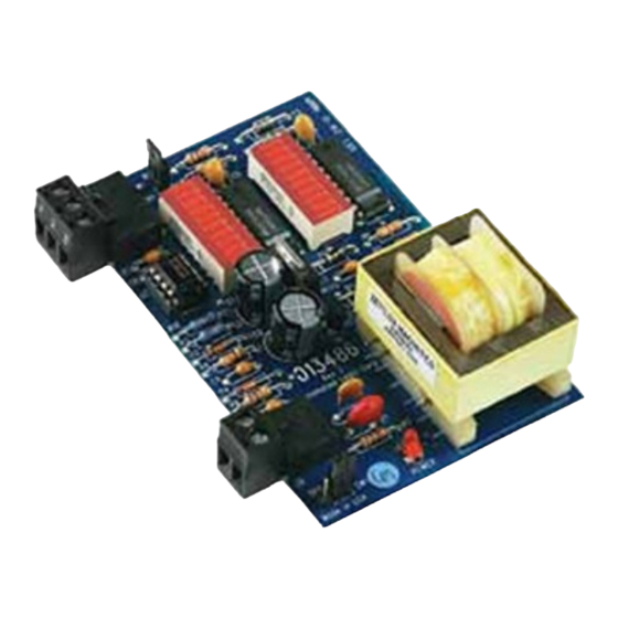
DIAG485
Mounting 2
Automated Logic Corporation • 1150 Roberts Blvd. • Kennesaw, GA 30144 • 770/429-3000 • 770/429-3001 Fax •
www.automatedlogic.com • Copyright 2003 Automated Logic Corporation. All rights reserved. Automated Logic, the
Automated Logic logo, SuperVision, Eikon, and Alert are registered trademarks of Automated Logic Corporation.
InterOp is a trademark of Automated Logic Corporation. BACnet
and product names are trademarked by their respective companies.
®
is a registered trademark of ASHRAE. All other brand
Advertisement
Table of Contents

Related Manuals for Automated Logic DIAG485


Summary of Contents for Automated Logic DIAG485
- Page 1 Diagnosing Network Problems 3 Protection 3 Automated Logic Corporation • 1150 Roberts Blvd. • Kennesaw, GA 30144 • 770/429-3000 • 770/429-3001 Fax • www.automatedlogic.com • Copyright 2003 Automated Logic Corporation. All rights reserved. Automated Logic, the Automated Logic logo, SuperVision, Eikon, and Alert are registered trademarks of Automated Logic Corporation.
- Page 2 Using the DIAG485 screws will be visible when the DIAG485 The DIAG485 (see Figure 1) is a diagnostic is installed. This prevents loose screws board that shows the communication signal from shorting out the back of the board.
- Page 3 Diagnosing Network Problems Figure 3 explains the meaning of some of the Good communications signals you may see on the DIAG485. The length of the network segment affects these displays; on a lengthy segment, fewer LEDs in One terminator missing each column may be illuminated.
Need help?
Do you have a question about the DIAG485 and is the answer not in the manual?
Questions and answers