
Related Manuals for Eagle Peak GHPC48V2-GRN-AZ


Summary of Contents for Eagle Peak GHPC48V2-GRN-AZ
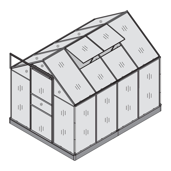
- Page 1 INSTRUCTION MANUAL EAGLE PEAK PC GREENHOUSE 6 FT x 8 FT x 7 FT Thank you for choosing Eagle Peak !
-
Page 2: Table Of Contents
CONTENTS 1. lmportant Read Before Assermbly ..........................1 2. Dimensions & Specifications ............................3 3. Part List ....................................4 4. Base Assembly ................................... 7 5. Vent Assembly ................................. 10 6. Door Assembly ................................13 7. Front Wall Assembly ..............................16 8. -
Page 3: Lmportant Read Before Assermbly
IMPORTANT Warning! To reduce the risk of serious injury, read the following safety instructions before assembling and using the greenhouse. Please check with your local governing authority/local municipal codes regarding installation of structures before assembly. Caution! Proper placement of your greenhouse is essential. Do not place the product underneath or near electrical lines. - Page 4 IMPORTANT • Please read and understand this manual before any assembly. Before beginning assembly of the product, make sure all parts are present. Compare parts with packaging contents list. • Place all parts from the box in a cleared area and organize them for assembly. •...
-
Page 5: Dimensions & Specifications
Dimensions & Specifications 1 . 9 2 0 7 6 . 8 1 3 8 4 . 5... -
Page 6: Part List
Part List Item Item Item Size Quantity Size Quantity Size Quantity Sketch Sketch Sketch 1215mm 1830mm 595mm 47.8in 72.0in 23.4in 1130mm 1300mm 520mm 44.5in 51.2in 20.5in 1130mm 594mm 595mm 44.5in 23.4in 23.4in 1130mm 1300mm 603mm 44.5in 51.2in 23.7in 1130mm 625mm 44.5in 24.6in 1640mm... - Page 7 Part List Item Size Item Item Quantity Quantity Quantity Sketch Sketch Size Sketch Size M6*40 202X M6*10 202X M3*20 M3*10 1830mm 27-1 72.0in 1220mm 27-2 48.0in 210X...
- Page 8 Part List Item Item Sketch Size Sketch Size 603x1120mm 603x1210mm 23.75x44.09in 23.75x47.63in 595x550mm 603x590mm 23.42x21.65in 23.75x23.22in 620x240mm 603x655mm 24.40x9.45in 23.75x25.78in 620x600mm 620x230mm 24.40x26.62in 24.40x9.05in 603x440mm 23.75x17.32in...
-
Page 9: Base Assembly
Step 1 Base Assembly Parts required for this step 1830 1220 27-1 27-2 M6*40 IMPORTANT: The ground, wooden deck, or concrete surface must be firm and level for maximum stability and durability. If not, the PC board may not be properly secured in the provided guide rail and may be blown out by strong wind. - Page 10 Step 1 Base Assembly, cont’d 27-1 27-2 27-2 27-2 27-1 27-2 27-2 Corner Stakes are needed to set up in soil (Status 1) 27-2 27-1 27-2 27-2 27-1 Assemble the foundation frame using (2) 27-2 Beams, (1) 32 Middle Bracket, and (4) 3 Screws, Nuts and Washers.
- Page 11 Base Assembly, cont’d Step 1 Assembly on 27-1 Ground Excavate the site by removing the top 3 in of grass or soil and leveling the base, allowing a 6 in perimeter around the foundation. Assembly on Wood or Concrete Pad Build a level wood or concrete pad Wooden Deck...
-
Page 12: Vent Assembly
Step 2 Vent Window Assembly Parts required for this step M6*10 595*550 M3*10... - Page 13 Step 2 Vent Window Assembly, cont’d...
- Page 14 Step 2 Vent Window Assembly, cont’d Repeat 2X Assemble (2) Frame piece 19B to (1) Frame piece 20B using (3) Screw Set 5. Do not tighten screws at this time. ① ② Slide Window E4 into the window frame. Secure the vent window handle 13 to the window frame using (2) screw 7.
-
Page 15: Door Assembly
Step 3 Door Assembly Parts required for this step 1600 M6*10 M3*20... - Page 16 Step 3 Door Assembly, cont’d Door pre-assembly for future step. PC Panels are not needed at this time.
- Page 17 Step 3 Door Assembly, cont’d Assemble Part 12A to Part 11A using (2) Screw, Washer and Nut 5. Assemble Part 12A/11A to (2) Vertical Door Frames Assemble Part 16A to (2) Vertical Door Frames 15A using (4) Screws 6. Repeat with second Part 16A as shown on Page Assemble Part 17A to (2) Vertical Door Frames 15A using (4) Screws 6.
-
Page 18: Front Wall Assembly
Step 4 Front Wall Assembly Parts required for this step 1215 1130 1130 1640 1640 1830 1300 M6*10... - Page 19 Step 4 Front Wall Assembly, cont’d Front Wall pre-assembly for future step. PC Panels are not needed at this time.
- Page 20 Step 4 Front Wall Assembly, cont’d 2A/2B Assemble Part 7D to Vertical Frames 2B using Assemble Corner Support 1A to Bottom (1) Screw, Washer, Nut 5. Repeat with 2A. Frame 5A using (1) Screw, Washer, Nut 5. Repeat at opposite end. Assemble Parts 7C, 7D, 1A and 1C to Corner Assemble Parts 7C, 7D, 1A and 1B to Corner Bracket 26 using (4) Screw, Washer, Nut 5.
-
Page 21: Door Slider Assembly
Step 5 Attach the Door Parts required for this step 1250 M6*40 M6*10... - Page 22 Step 5 Attach the Door, cont’d...
- Page 23 Step 5 Attach the Door, cont’d Slide (3) Screw 5 into the channel on upper Door Channel 13A. Attach Door Channel 13A to parts 6A and 1B using two of the three Screw 5. Attach the top of Vertical Support 14A Attach the bottom of Vertical Support 14A to the end of 13A using the remaining to Roof Beam 1B using Screw 3.
-
Page 24: Side Wall Assembly
Step 6 Side Wall Assembly Parts required for this step 1215 1220 1220 1300 1220 1220 M6*10... - Page 25 Step 6 Side Wall Assembly, cont’d...
- Page 26 Step 6 Side Wall Assembly, cont’d Slide (5) Screw 5 into the channel of Vertical Slide (4) Screw 5 into the channel of Vertical Wall Support 3C. Repeat 3X. Wall Support 3C. Repeat 1X. Connect Horizontal Beam 8B and 8C with Connector 20 using (8) Screw 5.
-
Page 27: Back Wall Assembly
Step 7 Back Wall Assembly Parts required for this step 1215 1215 1130 1130 1130 1130 1665 1665 1665 1665 1830 1830 1830 1830 M6*10... - Page 28 Step 7 Back Wall Assembly, cont’d Back Wall pre-assembly for future step. PC Panels are not needed at this time.
- Page 29 Step 7 Back Wall Assembly, cont’d 3A/3B Slide (5) Screw 5 into the channel of Attach Corner Vertical Support 1A to Vertical Wall Support 3A and 3B. Horizontal Beam 4B using (1) Screw Set 5. Repeat on opposite end with remaining Vertical Support 1A.
- Page 30 Step 8 Roof Ridge Beam Assembly Parts required for this step 1220 M6*10...
- Page 31 Step 8 Roof Ridge Beam Assembly, cont’d 1B/1C 1D/1E Insert Plug 19 into the ends Connect (2) Roof Ridge Beam 9B with Connector 21 using (4) Screw 5. of Diagonal Roof Braces 1B, 1C, 1D, and 1E.
- Page 32 Step 9 Joining the Walls Parts required for this step M6*10 9 .8 9 .8 9 .2 9 .3 9 .5 9 .1 9 .6 9 .5 9 .4 9 .7 9 .5 9 .1 9 .6...
- Page 33 Step 9 Joining the Walls, cont’d Place the Right Wall Assembly and Back wall Assembly on the Foundation Assembly with the help of an assistant. Attach the bottom of Vertical Support 1A to the end of Bottom Horizontal Beam 4C and 4D using (1) Screw 5 Set.
- Page 34 Step 9 Joining the Walls, cont’d 3A/3B/3C 27-2 27-2 27-1 Secure Wall Assemblies to the Foundation Assembly by removing the required nuts and washers, installing (8) Clip 29, and replacing the nuts and washers as shown. 2A/2B 27-1 Secure the Front Wall Assembly to the Remove the nut and washer from the Foundation by removing the nut and lower corner, install Clip 29 to attach the...
-
Page 35: Roof Frame Assembly
Step 10 Installing the Roof Rafters Parts required for this step 1115 M6*10... - Page 36 Step 10 Installing the Roof Rafters, cont’d Slide Slide the two Vent Panel Assemblies into the channel on Ridge Beam 9B as shown. 10 .6 10 .7 10.1 10 .6 10 .7 10.1 10.1 10 .2 10 .5 10 .8 10 .4 10 .7 10 .2...
- Page 37 Step 10 Installing the Roof Rafters, cont’d 10 .1 10 .2 Slide (5) Screw 5 into the channel Slide (6) Screw 5 into the channel on (3) Roof Rafter 3D. on (3) Roof Rafter 3D. 10 .3 10 .4 Attach the lower end of Roof Rafter 3D Attach the top end of Roof Rafter 3D to Roof Ridge to Sidewall Horizontal Beam 8B/8C using Beam 9B using the uppermost Screw 5.
-
Page 38: Panel Supports Assembly
Step 11 Installing the Panel Supports Parts required for this step 1830 M3*10 M6*10... - Page 39 Step 11 Installing the Panel Supports, cont’d 11 .1 11 .2 11.3 11.5 11.7 11.3 11.5 11.4 11.6 11.1 11.2 Install (2) T Braces 25 on Vent Support 10A using Attach Vent Support 10A to Roof (4) Screw 7. Repeat 1X. Rafters 3D using (2) Screw 5.
- Page 40 Step 11 Installing the Panel Supports, cont’d 11.3 11.4 1B/1C 1D/1E Attach (4) Horizontal Panel Supports 7K to Diagonal Roof Beam 1B, 1D and Roof Rafters 3D using (5) Screw 5. Repeat on opposite side. 11.5 11.6 Attach (4) Horizontal Panel Supports 7K to Vertical Wall Supports 1A and 3C using (5) Screw 5.
-
Page 41: Pc Panels Installation
Set up the PC Panels Parts required for this step 603*1210 603*1120 603*590 603*655 620*230 620*240 603*440 620*600... - Page 42 PC Panel Rear Side Roof Roof Side Front Notes: 1. Peel approximately 2 inches of film from all sheet edges before installing. Remove all film immediately after the constructions completed. 2. The UV-protected side of the sheet is covered with opal white film and must face towards the sun.
- Page 43 Step 12 Installing the PC Panels Use of a ladder may be necessary to reach the top of the greenhouse. The sides of the panels are secured using the Spring Clips 14. To place the clips insert one end into the frame channel. Then, capture the panel in the center of the clip as shown below.
- Page 44 Step 12 Installing the PC Panels, cont’d 12.4 12.7 12.3 12.2 12.5 12.6 12.1...
- Page 45 Step 12 Installing the PC Panels, cont’d 12.1 12.2 12.3...
- Page 46 Step 12 Installing the PC Panels, cont’d 12.4 12.5 8B/8C 12.6 12.7...
- Page 47 Step 13 Installing the Accessories Parts required for this step...
- Page 48 Step 13 Installing the Accessories, cont’d 13 .3 13.1 13 .4 13 .2 13 .3 13 .4 13.2 13 .4 13 .1...
-
Page 49: Rainwater Collection System
Step 13 Installing the Accessories, cont’d 13.1 13.2 8B/8C 8B/8C ATTENTION You may need a slotted screwdriver when you are assembling plug 10 & 9 13.4 13.3 Rotate... -
Page 50: Anchor The Base
Anchor the Base A drill will be needed to anchor A drill will be needed to anchor the greenhouse to concrete. the greenhouse to wooden deck. 27-1/27-2 27-1/27-2 Concrete Ground Wooden Deck... -
Page 51: Open And Close The Vents
Open and Close The Vents Attention: Make sure the vent is in the correct position before closing it. -
Page 52: Additional Strength
Additional Strength Advice You can also glue the polycarbonate panel to the aluminum frame to enhance the stability using silicone sealant. Note Silicone sealant and caulking gun are not included in our tool kit. You can buy them locally. Only use the silicone sealant suitable for aluminum.
Need help?
Do you have a question about the GHPC48V2-GRN-AZ and is the answer not in the manual?
Questions and answers