Table of Contents
Advertisement
Quick Links
Advertisement
Table of Contents

Related Manuals for Automation Direct D0-DEVNETS

Summary of Contents for Automation Direct D0-DEVNETS
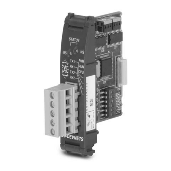
- Page 1 D0–DEVNETS DeviceNet Slave Module User Manual Manual Number D0–DEVNETS–M...
- Page 2 WARNING Thank you for purchasing automation equipment from Automationdirect.com. We want your new DirectLOGIC automation equipment to operate safely. Anyone who installs or uses this equipment should read this publication (and any other relevant publications) before installing or operating the equipment. To minimize the risk of potential safety problems, you should follow all applicable local and national codes that regulate the installation and operation of your equipment.
- Page 3 AVERTISSEMENT Nous vous remercions d’avoir acheté l’équipement d’automatisation de Automationdirect.comE. Nous tenons à ce que votre nouvel équipement d’automatisation DirectLOGIC fonctionne en toute sécurité. Toute personne qui installe ou utilise cet équipement doit lire la présente publication (et toutes les autres publications pertinentes) avant de l’installer ou de l’utiliser.
- Page 4 Manual Revisions If you contact us in reference to this manual, be sure to include the revision number. Title: D0–DEVNETS DeviceNet Slave Module User Manual Manual Number: D0–DEVNETS–M Edition Date Description of Changes Original 11/01 Original issue Rev. A 11/02 Added DL06 references...
-
Page 5: Table Of Contents
Table of Contents Chapter 1: Getting Started Introduction ............... . . 1–2 The Purpose of this Manual . - Page 6 Table of Contents Appendix C: Image Table Mapping Image Table Mapping ..............C–2 PLC Mode Image Table Mapping .
-
Page 7: Chapter 1: Getting Started
Getting Started In This Chapter..— Introduction — Introduction to DeviceNet — General Information About D0–DEVNETS... -
Page 8: Introduction
1–2 Getting Started Introduction The Purpose of This manual describes the installation and this Manual operation of the D0–DEVNETS Slave Module (D0–DEVNETS). Supplemental The following manuals are essential for the proper use of your DL05 DeviceNet Slave Module. Manuals • DL–05 Micro PLC User Manual part number D0–USER–M This manual contains very important information, including a complete I/O Module Memory Map. -
Page 9: Conventions Used
1–3 Getting Started Conventions Used The “light bulb” icon in the left-hand margin indicates a tip or shortcut. The “note pad” icon in the left–hand margin indicates a special note. The “exclamation mark” icon in the left-hand margin indicates a warning or caution. These are very important because the information may help you prevent serious personal injury or equipment damage. -
Page 10: Introduction To Devicenet
1–4 Getting Started Introduction to DeviceNet DeviceNet is a low-cost control bus used to connect field devices to PLCs and PCs. DeviceNet is designed to reduce the need for hard–wiring while providing device–level diagnostics. There are a host of manufacturers of DeviceNet products, offering an array of products including sensors, motor drives and starters, PLCs, pushbuttons, remote I/O systems, etc. -
Page 11: General Information About The D0-Devnets
1–5 Getting Started General Information about the D0–DEVNETS The D0-DEVNETS slave module offers the following features: The D0–DEVNETS installs into any of the DL05 PLC’s option slot. The PLC must have firmware version 3.0 or higher installed. The D0–DEVNETS can be installed in any of the four option slots of the DL06 PLC. -
Page 12: Chapter 2: Installing The Devicenet Slave Module
Installing the DeviceNet Slave Module In This Chapter..— Installing the D0–DEVNETS Slave Module — Configure the Adapter — D0–DEVNETS Parameter Setup — Software and Firmware Requirements — Writing the D0–DEVNETS Setup... -
Page 13: Installing The D0-Devnets Slave Module
2–2 Installing the D0–DEVNETS Slave Module Installing the D0–DEVNETS Slave Module Setting the DIP The DIP switch, SW1 must be set before installing the DeviceNet slave module in the Switch (SW1) DL05 option slot or in one of the DL06 option slots. The following diagram shows the location of the DIP switch. - Page 14 2–3 Installing the D0–DEVNETS Slave Module Set the DL05/06 to Slave Mode. When SW1–3 is ON, the DL05/DL06 can be placed in the RUN mode with the external RUN/TERM/STOP switch (with or without a program in it). Slave I/O Only Mode Mode SW1–3 Slave I/O only...
-
Page 15: Remove The Slot Cover
2–4 Installing the D0–DEVNETS Slave Module Remove the When the D0–DEVNETS module is ready to be installed the protective option slot Slot Cover cover must be removed. The protective cover is removed from the option card slot by squeezing the pinch tabs and lifting the cover off. Pinch Tabs Option Module Slot Covers... -
Page 16: Insert The Module
2–5 Installing the D0–DEVNETS Slave Module Insert the Module Insert the D0–DEVNETS slave module into the open card slot. Locate the module so the printed information is oriented in the same direction as the markings on the PLC. Be careful to align the female connector on the printed circuit board of the module with the male connector on the PLC mother board. -
Page 17: Set The Node Address
2–6 Installing the D0–DEVNETS Slave Module Set the Node Once the D0–DEVNETS is installed in the option slot, set the Node Address. The Address Node Address rotary switches are accessed by removing the cover located to the right of Port1 and Port2 on the DL05. STOP TERM Node Address... -
Page 18: Configure The Adapter
2–7 Installing the D0–DEVNETS Slave Module Configure the Adapter Configuring the Use the software of your DeviceNet master to configure the controller for your network. Refer to the software Help file and/or manual for help with configuration. DeviceNet Adapter Follow these basic steps when configuring your D0–DEVNETS adapter. 1. -
Page 19: Status Indicators
2–8 Installing the D0–DEVNETS Slave Module Status Indicators The adapter has two Status Indicators, one for Module Status and the other for STATUS Network Status. MS (Module Status) Indicator Indication Status No power to module. Solid Green Power is ON, normal condition Solid Red Critical module Failure NS (Network Status) Indicator... -
Page 20: D0-Devnets Parameter Setup
2–9 Installing the D0–DEVNETS Slave Module D0–DEVNETS Parameter Setup D0–DEVNETS The DL05/06 PLCs reserve several V–memory locations for storing the DEVNETS Default Parameters parameters. These special registers store the I/O ranges. The parameters are stored in the DL05/06 systems FLASH memory, and are not lost when the PLC is powered off. -
Page 21: Software And Firmware Requirements
2–10 Installing the D0–DEVNETS Slave Module Software and Firmware Requirements How to Update When a D0–DEVNETS module is installed, the DL05/06 PLCs do not need to have a Your DirectSOFT32 relay ladder logic (RLL) program in them to operate as slave I/O. However, if you are using the D0–DEVNETS in either a DL05 or a DL06 for local control on a network, Programming they must have a RLL control program in them. -
Page 22: How To Update Your Dl05 Firmware
2–11 Installing the D0–DEVNETS Slave Module The “CPU Version:” will tell you what firmware version is installed in your PLC. If your PLC requires new firmware, you may download the latest firmware and How to Update Your DL05 upgrade tool from our website. Point your browser to www.automationdirect.com, Firmware click on technical support, then select Firmware Upgrades. -
Page 23: Changing The D0-Devnets Setup Parameters
2–12 Installing the D0–DEVNETS Slave Module Changing the D0–DEVNETS Setup Parameters There may be a time when the initial setup parameters will need to be changed. The following example shows how to edit a DL05/06 PLC program to make the parameter changes using DirectSOFT32 programming software. -
Page 24: Appendix A: Specifications
Specifications In This Appendix..Specifications... - Page 25 A–2 Specifications Specifications General Specifications Ambient Operating Temperature 32°F to 131°F (0°C to 55°C) Storage Temperature –4°F to 158°F (–20°C to 70°C) Ambient Humidity 5% to 95% non-condensing Atmosphere No corrosive gases, max. environmental pollution = 2, UL840 Vibration Resistance MIL STD 810C, method 514.2 Shock Resistance MIL STD 810C, method 516.2...
- Page 26 A–3 Specifications DeviceNet Communication Details Device Type Generic Explicit Peer to Peer Message I/O Peer to Peer Message Configuration Consistency Fault Node Recovery Communication Baud Rate 125K, 250K, 500K Master/Scanner I/O Slave Message Bit Strobe Polling Cyclic Change of State (COS) DeviceNet Object Item...
- Page 27 Tables In This Appendix..DeviceNet Tables...
-
Page 28: Data Input And Output Tables
B–2 Tables Data Input and Output Tables I/O Assembly Object is used for Data Transfer of the LINK register. I/O Assembly Object can access the data of the Input Point, Output Point, Input V–memory and Output V–memory. The I/O Assembly Object can also control the PLC Mode. - Page 29 B–3 Tables Output Point Attribute Instance = 101 Attribute = 3 Name Data Address Service Output Point Output 07 ––––––––––– Output 00 Output 17 ––––––––––– Output 10 Output 27 ––––––––––– Output 20 Output 37 ––––––––––– Output 30 Output 47 ––––––––––– Output 40 Output 57 –––––––––––...
- Page 30 B–4 Tables Output Register Attribute Instance = 103 Attribute = 3 Name Data Address Service Output Register Vn+00 Vn+01 Vn+02 Vn+03 Vn+04 Vn+62 +124 Vn+63 + 126 The Data Register equals one Word (16 bits). A maximum of 64 V–memory words can be accessed. PLC Mode Control Attribute Instance = 104 Attribute = 3 Name...
-
Page 31: Device Profile Tables
B–5 Tables Device Profile Tables Identify Object (Class 1) Instance 1 Attribute Attribute Item Data type Value Service Vendor ID UINT Device Type UINT Product Code UINT 1500 Major Revision UINT Minor Revision UINT Status WORD Serial Number UDINT **** Product Name SHORT–STRING D0–DEVNETS... - Page 32 B–6 Tables Connection Object (Class 5) Slave Explicit Messaging Connection Object (Instance 1) Attribute Item Data type Value Service State UINT Instance Type UINT TransportClass_trigger BYTE Produced_connection_id UINT Consumed_connection_id UINT Initial_comm_characteristics BYTE Produced_connection_size UINT Consumed_connection_size UINT Expected_packet_rate UINT 2500 Watchdog_timeout_action USINT Produced_connection_path_length UINT...
- Page 33 B–7 Tables I/O Assembly Object (Class 4) Instance Attribute Instance Attribute Data type Description Bytes Service Maximum Input Data Output Data WORD Input Register Data WORD Output Register Data BYTE PLC Mode Get/Set Common Service Service Code Common Service Set_Attribute_Single Get_Attribute_Single Instance Attribute Instance...
-
Page 34: Appendix C: Image Table Mapping
Image Table Mapping In This Appendix..Image Table Mapping... - Page 35 C–2 Image Table Mapping Image Table Mapping Read, Write and Status Byte References D0–DEVNETS can access data bytes. Discrete Input Discrete Input Point (X,Y,C,S,T,CT,SP) Image Table Mapping Inputs Inputs I/O Image Inputs Input Size Inputs Read 1 to 8 bytes Inputs Inputs Inputs...
- Page 36 C–3 Image Table Mapping Discrete Output Point (X,Y,C,S,T,CT,SP) Image Table Mapping Outputs Inputs I/O Image Outputs Outputs Output Size Outputs Write 1 to 8 bytes Outputs Outputs Outputs Outputs Dec. Bit Size Oct. Bit Size Not Supported Read Byte 1 Write Byte 1 Write Byte 2 Write Byte 3...
- Page 37 C–4 Image Table Mapping Register Input (V–memory) Image Table Mapping I/O Image Low Byte Inputs Data Vn+00 High Byte Low Byte Inputs Data Vn+01 High Byte Low Byte Inputs Data Vn+02 High Byte Low Byte Inputs Data Vn+03 High Byte Input Size Low Byte Inputs Data Vn+04...
- Page 38 C–5 Image Table Mapping Vn + 08 V memory Low byte data Read Byte 17 Vn + 08 V memory High byte data Read Byte 18 Vn + 09 V memory Low byte data Read Byte 19 Vn + 09 V memory High byte data Read Byte 20 Vn + 30 V memory Low byte data Read Byte 60...
- Page 39 C–6 Image Table Mapping Register Output (V–memory) Image Table Mapping I/O Image Low Byte Outputs Data Vn+00 High Byte Low Byte Outputs Data Vn+01 High Byte Low Byte Outputs Data Vn+02 High Byte Low Byte Outputs Data Vn+03 High Byte Output Size Low Byte Outputs Data Vn+04...
- Page 40 C–7 Image Table Mapping Vn + 07 V memory Low byte data Write Byte 15 Vn + 07 V memory High byte data Write Byte 16 Vn + 08 V memory Low byte data Write Byte 17 Vn + 08 V memory High byte data Write Byte 18 Vn + 09 V memory Low byte data Write Byte 19...
-
Page 41: Plc Mode Image Table Mapping
C–8 Image Table Mapping PLC Mode Image Table Mapping I/O Image Input Size Inputs Read 1 byte 00:RUN Mode 03:STOP Mode Output Size Outputs Write 1 byte 01:RUN Request 02:STOP Request Dec. Bit Size Oct. Bit Request Read Byte 1 Read Byte 1 STOP Request... -
Page 42: Appendix D: Special Relays And Dip Switch Parameter Initializing
Special Relays and DIP Switch Parameter Initializing In This Appendix..Special Relays DIP Switch Parameter Initializing... -
Page 43: Network Status Speicial Relays
D–2 Special Relays Network Status Speicial Relays The DL05 has special relays which allows the D0–DEVNETS to monitor the network status. These relays are SP120 and SP121. Condition Details Communicating SP120 SP120 No communication Communication error SP121 SP121 Normal Initializing Parameter Values The values of the system parameter registers, V7610 –... -
Page 44: Appendix E: D0-Devnets Think & Do/Entivity Setup
D0–DEVNETS Think & Do/Entivity Setup In This Appendix..D0-DEVNETS Think & Do/Entivity Setup... -
Page 45: D0-Devnets Think & Do/Entivity Setup
E–2 Think & Do Setup D0–DEVNETS Think & Do/Entivity Setup For those who are using the D0–DEVNETS as slave I/O with Think & Do Studio PC based control, the following example shows how to setup Think & Do on your network. - Page 46 E–3 Think & Do Setup 7. Click on connection. Think & Do/Entivity will display D0–DEVNETS MacID #. PIn and POut will display 32 points each. 8. Click on Scan and communication will begin. PIn 01 will display diagnostic data. POut 01 controls D0–DEVNETS. Inputs X0–X7 (V40400) will display on bits 0–15 of PIn 02.
-
Page 47: Setup Think & Do With Dl05 On A Network
E–4 Think & Do Setup For those who are using a DL05 with D0–DEVNETS as a PLC, for local I/O control, on a DeviceNet network with Think & Do Studio, the following example shows how to setup the DL05 and the adapter for use as a PLC on the network. Setup Think &... -
Page 48: T & D Studio Setup
E–5 Think & Do Setup T & D Studio setup Use the following procedure to setup the D0–DEVNETS adapter with Think & Do Studio. 1. Click on Add Driver and SST card is installed. 2. Set MAC ID to 62. 3. - Page 49 E–6 Think & Do Setup 7. Click on connection. 8. Click on Scan and communication will be setup. POut 01 controls D0–DEVNETS. PIn 01 is system information. PIn 02 is V40400 and PIn 03 is linked to POut 02 is linked to V40500. V40401 which shows the active inputs.
- Page 50 E–7 Think & Do Setup The following example is a DL06 PLC with the following I/O modules installed: Slot 1 = D0–16ND3 Slot 2 = F0–2AD2DA–2 Slot 3 = D0–10TD2 Slot 4 = D0–DEVNETS PIn 01 is input diagnostic data POut 01 is diagnostic control bits (16) Unused bits PIn 02–03 Inputs...
- Page 51 E–8 Think & Do Setup This is how the display appears after scanning begins. Notice the end points for the DL06 integrated I/O. Only the discrete I/O is polled. Analog I/O is setup in registers (See page 2–11). Last integrated input, X23. Last integrated output, Y17.
-
Page 52: Appendix F: Oit With D0-Devnets
OIT with D0–DEVNETS In This Appendix..OIT with D0-DEVNETS and Think & Do/Entivity... -
Page 53: Using An Oit With D0-Devnets
F–2 OIT and Think & Do Using an OIT with D0–DEVNETS An Operator Interface Terminal (OIT) can be used on your DeviceNet network. The example used here is for a D0–DEVNETS installed in a PLC on a DeviceNet network. The network is controlled by a PC, with an SST module installed and using Think &... - Page 54 F–3 Think & Do Setup Our example uses three flowcharts. Flowchart 1 Gets the data, flowchart 2, entitled Parsing, breaks down the data and flowchart 3 Sends the data. We will select GetUpdateOn first. D0–DEVNETS DeviceNet Slave Module User Manual, Rev A...
- Page 55 F–4 OIT and Think & Do This flowchart shows how to set up explicit messaging to Get (receive) the data. Once the explicit messaging is done, it normally turns off, but in this example, the last block provides a 500 millisecond delay which allows the explicit messaging to turn on again. Refer to the DeviceNet tables located in Appendix B when creating your flowcharts.
- Page 56 F–5 Think & Do Setup Since Think & Do Studio has 32 bit registers, the 32 bits must be broken down into two 16 bit registers in order to transmit (send) the correct data to the PLC. This flowchart, Parsing, shows how it is done. D0–DEVNETS DeviceNet Slave Module User Manual, Rev A...
- Page 57 F–6 OIT and Think & Do This flowchart, SendUpdateOn, shows you how to put the data into a send (transmit) buffer. The data gets cleared out of the buffer whenever each explicit messaging is done, therefore, data needs to be loaded into the buffer before each explicit messaging is turned on.
- Page 58 F–7 Think & Do Setup After Think & Do has been setup, the EZTouch panel can be connected to the DL05/06 serial port. Match the communications settings in the EZTouch software to the settings for the DL05/06 serial port setup. From the development screen, select Setup then PLC..
- Page 59 F–8 OIT and Think & Do This is an example of a meter display and two numeric entry parts showing the use of the default V–memory input and output locations. D0–DEVNETS DeviceNet Slave Module User Manual, Rev A...
- Page 60 F–9 Think & Do Setup Finish the EZTouch display by completing the input and output information. Consult the EZTouch User Manual or the EZTouch help menu for more details. D0–DEVNETS DeviceNet Slave Module User Manual, Rev A...
-
Page 61: Appendix G: D0-Devnets And Allen-Bradley Set Up
D0–DEVNETS and Allen–Bradley Set up In This Appendix..Setup D0-DEVNETS with Allen-Bradley RSNetworxt... -
Page 62: Setup D0-Devnets With Allen-Bradley Rsnetworxt
G–2 Allen–Bradley Setup Setup D0–DEVNETS with Allen–Bradley RSNetWorxt For those who are using the D0–DEVNETS as a slave with an Allen–Bradley PLC, the examples on the following pages will step you through the process of setting up your Allen–Bradley DeviceNet network using RSNetWorxt. RSLinx Begin by opening your RSLinx to configure the DeviceNet driver. - Page 63 G–3 Allen–Bradley Setup 5. Click OK in the pop–up window. This window will appear. 6. Click on Auto–Configure to setup the communication parameters. Auto Configuration Successfull will appear. 7. Click OK D0–DEVNETS DeviceNet Slave Module User Manual, Rev A...
- Page 64 G–4 Allen–Bradley Setup The Configure Drivers window will now appear showing the Status as Running. The next step is to add a DeviceNet driver. 8. Click on the down arrowhead, , and select your choice of drivers from the drop–down list. 9.
- Page 65 G–5 Allen–Bradley Setup The DeviceNet Interface Configuration window will appear briefly. This window will appear for you to setup the pass through port. Be sure that you select the proper slot where the scanner module is located. If this does not match, you will need to reconfigure the I/O in RSLogix.
-
Page 66: Rslogix
G–6 Allen–Bradley Setup RSLogix You are ready to connect to the PLC using your RSLogix software. 1. Click on Communications and select Who Active Go Online. 2. When this window appears, select the PLC to connect 3. Click OK. This window will appear with the relay ladder program. - Page 67 G–7 Allen–Bradley Setup The I/O Configuration window will come into view. When you select the scanner module, verify that it is in the correct slot. 5. Click Adv Config. The Advanced I/O Configuration window will appear. The M0 and M1 Lengths will show the default of 256.
-
Page 68: Configure D0-Devnets With Rsnetworx
G–8 Allen–Bradley Setup Configure You are now ready to configure the D0–DEVNETS installed in your DL05. First, open D0–DEVNETS with RSNetWorx. Look for Koyo Electronics in the hardware tree listed under Vendor. Click on the + to show the devices for Koyo. The following example shows two RSNetWorx devices, D0–DEVNETS and T1K–DEVNETS. - Page 69 G–9 Allen–Bradley Setup The EDS Wizard will open. Simply follow the instructions to register the device. Register the EDS file. Enter the path for the EDS file. D0–DEVNETS DeviceNet Slave Module User Manual, Rev A...
- Page 70 G–10 Allen–Bradley Setup EDS file installation results. Change the icon image for your device, if you desire to. Review what you have done. D0–DEVNETS DeviceNet Slave Module User Manual, Rev A...
-
Page 71: Go On Line
G–11 Allen–Bradley Setup EDS Wizard complete. Go on line You will want to go on line with the network now. In the main RSNetworx window, 1. Click on Network to select Online. 2. Select your network from the pop–up window. 3. -
Page 72: Set Up I/O Parameters
G–12 Allen–Bradley Setup This message will appear. 4. Click OK. Browsing network message. Once the nodes are found, each node icon will appear on the RSNetworx window. After all of the nodes have been found, browse can be cancelled. Set up I/O Now you can set up the I/O paramerters for the devices. - Page 73 G–13 Allen–Bradley Setup The properties window will appear. 4. Click Module. 5. Click Upload. Uploading network information. Note: Do not cancel. The entire network data must be allowed to upload. The data appears. 6. Select the correct slot number which the DeviceNet scanner module is residing.
- Page 74 G–14 Allen–Bradley Setup If the node that you want is not in the Scanlist, it needs to be moved to the list. 8. Highlight D0–DEVNETS 9. Click the right arrow. Now that D0–DEVNETS is in the list, be sure that it is selected.
-
Page 75: Map The Nodes
G–15 Allen–Bradley Setup This window will appear. 13. Click Yes. Map each node. Map the nodes 1. Click the Input tab in the properties window. Be sure that D0–DEVNETS is selected. 2. Select Discrete for Memory, and 0 for Start Word. 3. - Page 76 G–16 Allen–Bradley Setup Now, map the outputs just the way you mapped the inputs. This time: 1. Click the Output tab in the properties window. Be sure that D0–DEVNETS is selected. 2. Select Discrete for Memory, and 0 for Start Word. 3.
- Page 77 G–17 Allen–Bradley Setup Download the scanlist to the scanner. 1. Select the Scanlist tab in the properties window. 2. Select Download to Scanner. In the pop–up window: 3. Check All Records, then 4. Click Download. Note: Verify that the processor is in program mode before downloading the scanlist. This is an error message that may appear.
-
Page 78: Set Class Instance Attribute
G–18 Allen–Bradley Setup Set Class Instance Use the Service Class Instance Attribute Editor to set the I/O to read and write to the Attribute DL05/06. 1. Select the D0–DEVNETS node. 2. Select Device 3. Right click on the node symbol in the RSNetWorx window.
Need help?
Do you have a question about the D0-DEVNETS and is the answer not in the manual?
Questions and answers