Advertisement
Quick Links
F u n c t i o n a l M o d e l
Parts List
base plate
wheels
battery holder
micro slide switch
jumper wire
motor
round rod
round rod
pulley wheel
rubber ring
reducer
PVC-tube
D208257#1
208.257
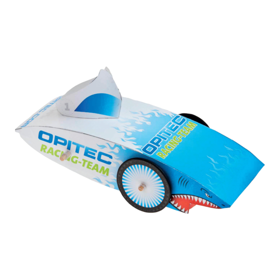
E l e c t r i c C a r
The OPITEC range of projects is not intended as play toys
for young children.They are teaching aids for young peop-
These projects should only be undertaken and tested with
Quantity
Size (mm)
1
4
1
1
1
1
1
1
1
1
1
1
Please Note
le learning the skills of Craft, Design and Technology.
the guidance of a fully qualified adult.
The finished projects are not suitable to give to children
under 3 years old. Some parts can be swallowed. Danger
of suffocation!
Description
7x5
base plate
ø 50
wheels
power source
19x6
switch
500
cabling
drive
ø 100x4
axis
ø 100x5
axis
ø 50
drive wheel
ø 40 transmission rubber
4/2
drive
ø 6
spacer
Required Tools:
Pencil & Ruler
Scissors
All Purpose Glue
Side Cutters
Craft Knife
Wire Strippers
Hot Glue Gun
Hole Punch
Piece of Cardboard (approx.
100 x 50 mm)
Part No.
1
2
3
4
5
6
7
8
9
10
11
12
1
1
Advertisement

Subscribe to Our Youtube Channel
Related Manuals for Opitec 208.257


Summary of Contents for Opitec 208.257
- Page 1 Piece of Cardboard (approx. 100 x 50 mm) Please Note The OPITEC range of projects is not intended as play toys for young children.They are teaching aids for young peop- le learning the skills of Craft, Design and Technology. These projects should only be undertaken and tested with the guidance of a fully qualified adult.
- Page 2 Instructions Step 1: Cut the cut-outs a and b out of the base plate with a craft knife. glue glue glue glue Step 3: Step 4: Step 2: Coat the bent up ends with glue, Glue the switch (4) in the cut out b, as Cut in a hole width at the ends of the fold up the sides and hold them with shown!
- Page 3 Instructions Step 7: Step 8: Put the reducer (11) onto the motor shaft as shown. Glue the motor into the base frame with hot glue gun in such a way that the rubber ring (10) is tightened when it is placed on the reducing piece (11) of the motor shaft.
- Page 4 Instructions Step 11: Step 12: Step 13: Glue two cardboard wheels (3) together. Fit the two wheels on both sides of the Cut out 4 pieces 25 x 50 mm each from a Then cut both wheels out of the templa- axle, align and glue them to the axle! piece of cardboard (approx.
Need help?
Do you have a question about the 208.257 and is the answer not in the manual?
Questions and answers