
Subscribe to Our Youtube Channel
Related Manuals for Instron 2620-600 Series


Summary of Contents for Instron 2620-600 Series
- Page 1 2620-600 Series Dynamic Strain Gauge Extensometers Reference Manual - Equipment M26-16655-EN Revision A The difference is measurable ®...
- Page 2 Trademarks Instron® is a registered trademark of Illinois Tool Works Inc. (ITW). Other names, logos, icons and marks identifying Instron products and services referenced herein are trademarks of ITW and may not be used without the prior written permission of ITW.
- Page 3 • carrying out your own safety risk assessment on the use of the test system, test methods employed, specimen loading and specimen behavior at failure. Product Support: www.instron.com...
- Page 4 Preliminary Pages General Safety Precautions Instron products, to the best of its knowledge, comply with various national and international safety standards, in as much as they apply to materials and structural testing. We certify that our products comply with all relevant EU directives (CE mark).
- Page 5 Whenever you consider that safety may be compromised, stop the test using the Emergency Stop button. Investigate and resolve the situation that caused the use of the Emergency Stop button before you reset it. Product Support: www.instron.com...
- Page 6 Preliminary Pages Warnings Flying Debris Hazard - Wear eye protection and use protective shields or screens whenever any possibility exists of a hazard from the failure of a specimen, assembly or structure under test. Wear eye protection and use protective shields or screens whenever a risk of injury to operators and observers exists from the failure of a test specimen, assembly or structure, particularly where explosive...
- Page 7 Disconnect equipment from the electrical power supply before removing any electrical safety covers or replacing fuses. Do not reconnect the power source while the covers are removed. Refit covers as soon as possible. Product Support: www.instron.com...
- Page 8 Preliminary Pages viii M26-16655-EN...
-
Page 9: Table Of Contents
2620-603 ..... . . 2620-604 ..... . . Product Support: www.instron.com... - Page 10 Preliminary Pages mM26-16655-EN...
-
Page 11: Chapter 1 Introduction
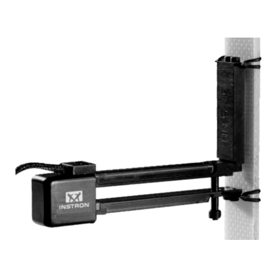
Chapter 1 Introduction General Description Instron Dynamic Strain Gauge Extensometers are accurate, lightweight strain gauge units used for accurate direct measurement and closed-loop control of strain in cyclic high frequency materials testing applications. Tensile, compressive, low and high cycle fatigue testing as well as straight line (ramp) testing may be performed with these devices. - Page 12 Instron static testing instruments. However only the Model 1121 table model and the Model 1190 floor model instruments can be fitted with the Instron Load/Strain control necessary to permit strain-controlled testing to be achieved. M26-16655-EN...
- Page 13 The extensometer can be quickly and easily calibrated, the method varies depending on the testing instrument and control console being used. A full description of all calibration procedures is detailed in a later section of this manual. Refer to “Calibration” on page 2-11 Product Support: www.instron.com...
- Page 14 Chapter: Introduction If you have a test situation for which you need specific information, contact your local Instron Sales Office or technical support team. M26-16655-EN...
-
Page 15: Operation
Chapter 2 Operation • Handling Precautions ..2-1 • Preparing for Use ... . . 2-3 • Mounting the Extensometer ..2-5 •... - Page 16 Chapter: Operation • Protect the extensometer from mechanical shocks. Do not allow it to drop and do not allow tools and other equipment to strike it. Be careful about placing the extensometer on a flat surface where the electrical connector, which is significantly heavier than the extensometer, can pull the extensometer onto the floor.
-
Page 17: Preparing For Use
Product Support: www.instron.com... - Page 18 Chapter: Operation The long extenders (37.5 mm or 40 mm) are installed in a similar manner, except that four short screws are used. Attach the knife edge to the extender before attaching the extender to the beam. Use the ball end of the hexagon wrench to tighten the two screws through the lower lip of the extender Inspect the extensometer for free operation...
-
Page 19: Mounting The Extensometer
It should be positioned on the frame adjacent to the extensometer assembly, such that the full weight of the cable is removed from the extensometer to prevent strain measurement errors. Product Support: www.instron.com... - Page 20 Chapter: Operation Figure 2-1. Extensometer Mounted with Rubber Bands Care must be taken not to nick or scratch the test sample with the hardened steel knife edges. Nicks and scratches, particularly on softer samples can be caused by a clamping spring or rubber band that is too tight and will result in the growth of fatigue cracks in the specimen that will render acquired test data...
- Page 21 3. While holding the extensometer in the left hand, place it against the specimen and hook a clamping spring or rubber band to the far side of the upper knife edge. Product Support: www.instron.com...
- Page 22 Chapter: Operation Preparation for Mounting Figure 2-2. 4. Hold the extensometer and the clamping device in place with the fingers of the right hand. Using the crochet hook, slip the near end of the clamping device over the other end of the knife edge. The extensometer will tend to rotate around the specimen, so ensure that the extensometer does not slip from the...
- Page 23 7. To prevent strain measurement errors, support the electrical cable so that the full weight of the cable is removed from the extensometer. Take up most of the Product Support: www.instron.com...
- Page 24 Chapter: Operation Installing the Lower Clamp Figure 2-4. slack in the cable and either tape it to the load frame column of other fixed object or use the magnetic cleat to support the cable. Leave a loop or some slack in the cable so that the extensometer is free to move without being pulled by the cable.
-
Page 25: Calibration
Once the pin is out, do not move the extensometer on the specimen or the calibrated gauge length will be lost. Calibration To ensure that the Extensometer indicates precisely the relative movement of the specimen, the device should be zeroed and calibrated before use. Product Support: www.instron.com 2-11... -
Page 26: Electrical Calibration
Electrical Calibration 1. The Extensometer is equipped with a memory device that will identify itself uniquely to an Instron controller, so that basic calibration data does not need re- inputting every time the gauge is moved. 2. Connect the plug into the 25-way transducer socket on the load frame. -
Page 27: Manual Calibration
The Extensometer may be used over a wide range of temperatures. Ideally, you should calibrate the gauge as close as possible to the actual temperature at which you expect the testing to take place. Any variation between the testing temperature and the temperature Product Support: www.instron.com 2-13... - Page 28 Chapter: Operation at which you calibrate the gauge will introduce a small error. Electrical calibration (using the internal shunt resistance) is only valid at, or close to, 20°C. If you are calibrating the span of the gauge at a temperature outside the range 10°C - 30°C, use a manual calibration procedure.
-
Page 29: Chapter 3 Maintenance
Chapter 3 Maintenance • Routine Maintenance ..3-1 • Replacement Parts... . . 3-2 Routine Maintenance Routine maintenance is limited to keeping the extensometer clean and the moving parts free. -
Page 30: Replacement Parts
Damaged or lost accessories can be replaced, using the following list, by contacting the nearest Instron Sales Office. The catalog number of the extensometer must be specified, along with the part number and item description when ordering parts. - Page 31 66-1-76 Tension Spring, in. long 66-1-77 Tension Spring, in. long 66-1-75 Tension Spring, 1 in. long 66-1-78 Tension Spring, 1 in. long 66-1-79 Tension Spring, 1 in. long 66-1-80 Rubber Bands (Packet of 50) A1351-1010 Product Support: www.instron.com...
- Page 32 Chapter: Maintenance M26-16655-EN...
-
Page 33: Appendix A Specification
Appendix A Specification General The following specifications are common to all the Extensometers described in this manual. Parameter Value Linearity 0.15% of Full Scale Hysteresis 0.15% FS @ 60% Full Scale Creep 0.15% of Full Scale Operating Force (2620-601,-602, -603) 150g (2620-604) 75g Output Sensitivity 2.5 mV/V (nominal) - Page 34 Chapter: Specification Parameter Value Temperature -80ºC to +200ºC (-100ºF to Range +400ºF) Overtravel Mechanical Stops Gauge Length Removable Pin Setting and Lock Attachment Special High Tear Strength Rubber Bands or Tension Springs Weight (less cable Less than 20 grams and connector) Specimen Sizes Round - 3 mm to 25 mm diameter...
-
Page 35: Compatibility
General Compatibility The extensometers may be used with any of the following Instron equipment: Table Model Servohydraulic Static Testers Dynamic Machines: 1120 Series 8800 Series 1185 Series 8500 Series 1190 Series 8000 Series 1195 Series 1270 Series 1197 Series 1250 Series... - Page 36 Chapter: Specification 2620-601 Extension length (mm) none 12.5 37.5 Gauge Length (mm): 12.5 Full Scale range (mm) ± 5 ± 5 ± 5 Maximum Strain Frequency Range (Hz) 0 - 50 0 - 50 0 - 50 2620-602 Extension length (mm) none 12.5 37.5...
-
Page 37: 2620-604
0 - 100 2620-604 Extension length (mm) Gauge Length (mm): Full Scale range (mm) +12.5 / -2.5 +12.5 / -2.5 Maximum Strain (%) +50 / -10 +25 / -5 2620-604 is not used without a gauge length extender. Product Support: www.instron.com... - Page 38 Chapter: Specification M26-16655-EN...
- Page 39 ..overtravel ..frequency range ..A-4 . . . full scale ..resistance routine maintenance Product Support: www.instron.com Index-1...
- Page 40 ..rubber bands ..safe operation safety . . . risk assessment ..training ..sensitivity .
- Page 41 Addresses Worldwide Headquarters Instron 825 University Avenue Norwood, MA 02062-2643 United States of America European Headquarters Instron Coronation Road High Wycombe, Bucks HP12 3SY United Kingdom Industrial Products Group Instron 900 Liberty Street Grove City, PA 16127 United States of America...
- Page 42 Product Support: www.instron.com...
Need help?
Do you have a question about the 2620-600 Series and is the answer not in the manual?
Questions and answers