
Related Manuals for Instron 2630-100 Series


Summary of Contents for Instron 2630-100 Series
- Page 1 2630-100 Series Clip-On Extensometer Reference Manual - Equipment M20-52630-1 Revision H The difference is measurable ®...
- Page 2 ITW. Trademarks Instron® is a registered trademark of Illinois Tool Works Inc. (ITW). Other names, logos, icons and marks identifying Instron products and services referenced herein are trademarks of ITW and may not be used without the prior written permission of ITW.
- Page 3 Caution is used where a hazard may lead to damage to equipment or to loss of data. • carrying out your own safety risk assessment on the use of the test system, test methods employed, specimen loading and specimen behavior at failure. Product Support: www.instron.com...
- Page 4 Preliminary Pages General Safety Precautions Instron products, to the best of its knowledge, comply with various national and international safety standards, in as much as they apply to materials and structural testing. We certify that our products comply with all relevant EU directives (CE mark).
- Page 5 Keep clear of the hazard area between the grips or fixtures during actuator or crosshead movement. Ensure that all actuator or crosshead movements necessary for installation or removal are slow and, where possible, at a low force setting. Product Support: www.instron.com...
- Page 6 Preliminary Pages Warnings Hazard - Press the Emergency Stop button whenever you consider that an unsafe condition exists. The Emergency Stop button removes hydraulic power or electrical drive from the testing system and brings the hazardous elements of the system to a stop as quickly as possible.
- Page 7 Protect all electrical cables, particularly transducer cables, from damage. Never route cables across the floor without protection, nor suspend cables overhead under excessive strain. Use padding to avoid chafing where cables are routed around corners or through wall openings. Product Support: www.instron.com...
- Page 8 Preliminary Pages Warnings Hazard - Set the appropriate limits before performing loop tuning or running waveforms or tests. Operational limits are included within your testing system to suspend motion or shut off the system when upper and/or lower bounds of actuator or crosshead travel, or force or strain, are reached during testing.
- Page 9 The actuator or crosshead will immediately respond to manual control settings when the system is placed off-line from computer control. Before transferring to manual control, make sure that the control settings are such that unexpected actuator or crosshead movement cannot occur. Product Support: www.instron.com...
- Page 10 Preliminary Pages Warnings Rotating Machinery Hazard - Disconnect power supplies before removing the covers to rotating machinery. Disconnect equipment from all power supplies before removing any cover which gives access to rotating machinery. Do not reconnect any power supply while the covers are removed unless you are specifically instructed to do so in the manual.
- Page 11 Apply the specified torque to all load string fasteners and the correct setting to wedge washers or spiral washers. Visually inspect highly stressed components such as grips and threaded adapters prior to every fatigue test for signs of wear or fatigue damage. Product Support: www.instron.com...
- Page 12 Preliminary Pages M20-52630-1-EN...
-
Page 13: Table Of Contents
Manual Mechanical Calibration ..Verification......Product Support: www.instron.com... - Page 14 Preliminary Pages Care of the Extensometer....Routine Maintenance ....Storing your Extensometer .
-
Page 15: Chapter 1 Introduction
The gauges are arranged in a fully active four-arm Wheatstone Bridge circuit. The 2630-100 series of extensometers includes different gauge lengths/strain range options to suit a wide range of specimen characteristics. -
Page 16: Extensometer Features
Chapter: Introduction The robust construction of the extensometer provides accuracy and reliability. When not in use, the extensometer should be stored in the case supplied with it. Extensometer Features • Ergonomic, lightweight, cross-braced design with overload protection. • Easy attachment and release from the specimen facilitate single-handed operation. - Page 17 • High impact plastic storage case with a contour moulded insert to securely retain the extensometer and accessory parts together with its Calibration Certificate and manual. Product Support: www.instron.com...
-
Page 18: Equipment Supplied
Chapter: Introduction Equipment Supplied Figure 1. Extensometer 2. Cable cleat and extensometer holder 3. 1.5 mm hexagon wrench 4. 11 pairs of wire clips 5. Specimen centering stops 6. This manual 7. Calibration certificate 8. Foam lined case For optional accessories and spares, Appendix M20-52630-1-EN... - Page 19 Equipment Supplied Case Manual Extensometer Cable Cleat and Extensometer Holder Hexagon Wrench Specimen Clips for Clips for Stops Rectangular Round Specimens Specimens Figure 1. Case Layout Product Support: www.instron.com...
- Page 20 Chapter: Introduction M20-52630-1-EN...
-
Page 21: Preparation For Testing
Attaching the extensometer by setting the gauge length and mounting the extensometer on the specimen. • Calibrating the extensometer. This needs to be done at the start of a test session or if you change specimen type. Product Support: www.instron.com... -
Page 22: Configuring The Extensometer
Chapter: Preparation for Testing This preparation chapter also covers care of the extensometer. Configuring the Extensometer Fitting Wire Clips Figure 2. Insertion of Clips Clips are available in two profiles to accommodate round and rectangular specimens. It is important for good results to select the clip that best suits the specimen. -
Page 23: Knife Edge Changing
Once the wire clip is selected and a test specimen is correctly installed in the testing machine grips the extensometer can be attached. Figure 3. Wire Clips in Use Knife Edge Changing Figure 1. Loosen the socket head cap screw using the supplied allen key. Product Support: www.instron.com... -
Page 24: Specimen Centering Stops
Chapter: Preparation for Testing 2. Position replacement knife edge with the bevel side of the knife edge furthest from the cut-out in the extensometer arms. 3. Secure with socket head cap screw ensuring alignment faces of the knife edge and extensometer touch. Socket Head Cap Screw Knife Edge Extensometer... -
Page 25: Attaching The Extensometer
Gauge Length Setting Before strain can be accurately measured the extensometer arms must be spaced to set the knife edges at gauge length. The extensometer features an integral cone latch arm locating system. Product Support: www.instron.com... - Page 26 Chapter: Preparation for Testing Cone Cone Pin Seat Round Round Button Button Figure 6. Gauge Length Setting with the Cone-Latch Released To set gauge length: 1. Press the two round buttons with index finger and thumb of either left or right hand.
- Page 27 (see Figure 6 Figure Figure 7. Gauge Length Setting with the Cone-Latch Engaged (Gauge Length Set) Verification of gauge length may be confirmed by engaging the gauge length Product Support: www.instron.com...
-
Page 28: About Mounting To Specimen
Chapter: Preparation for Testing cone latch and checking the distance between the knife edges using either calipers or a slip gauge. About Mounting to Specimen Normally, we recommend that you install the specimen in your grips and then attach the extensometer. Refer to your system documentation for specimen installation details. -
Page 29: Mounting To The Specimen Using Both Hands
2. Using the other hand open the wire clips to clear the specimen, as shown Figure 3. Position the extensometer in line with the specimen and gradually release the clips. Product Support: www.instron.com... -
Page 30: Mounting To The Specimen Using One Hand
Chapter: Preparation for Testing 4. Once the extensometer is attached to the specimen, release the gauge length cone-latch. If the extensometer is not held firmly onto the specimen select a smaller clip. Mounting to the Specimen using One Hand Press Cone Latch to set Gauge Length Clip Prong Figure 9. -
Page 31: Elastic Bands Or O-Rings
Elastic Bands or O-Rings Hooks for elastic bands or O-rings are an integral part of the knife edges, although elastic bands and O-rings are not supplied with the extensometer. See page O-ring details. Product Support: www.instron.com... -
Page 32: Variable Pressure Specimen Clamp
Chapter: Preparation for Testing 1. Hold the extensometer with the gauge length cone latch engaged and position the knife edges on the test specimen. 2. Stretch good quality elastic bands or O-rings around the specimen and loop the ends over the two knife edge hooks, as shown in Figure Figure 10. - Page 33 3. Press the clamp against the specimen to compress the spring loaded plunger and hook the specimen clamp on the knife edges. Ensure that the knife edge seats properly in the specimen clamp notch pivot. Product Support: www.instron.com...
-
Page 34: Calibration
Three methods of calibration are possible: Automatic Electrical Calibration This is the normal method of calibration for current Instron testing machines. The extensometer is self-identifying via its code resistors. These are interrogated by the testing machine which has the calibration parameters stored within its memory. -
Page 35: Manual Electrical Calibration
Calibration Instron machine check its compatibility with automatic calibration on page 50. To operate the automatic electrical calibration, refer to the operating instructions or user’s guide supplied with the testing machine. Before starting the calibration, ensure that the extensometer is set at gauge length, and is correctly attached to the test specimen. -
Page 36: Manual Mechanical Calibration
A calibration fixture is required for manual mechanical calibration. Contact your local Instron representative for details of manual mechanical calibration and appropriate calibration fixtures. Verification The achievable ISO or ASTM classification is given in “Gauge Lengths and Travel”... -
Page 37: Care Of The Extensometer
• Inspect the cable and connector for wear or damage. Storing your Extensometer When the extensometer is connected to the controller, but not being used for testing, use the holder provided (see “Extensometer Holder” on page 38). Product Support: www.instron.com... -
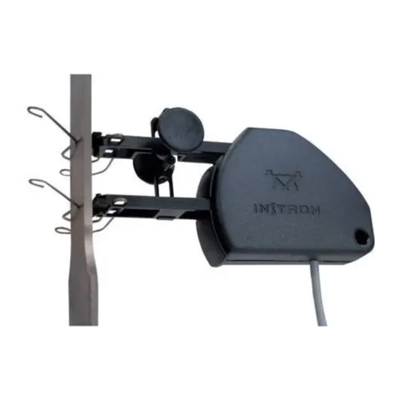
Page 38: Repair
Repair There are no field serviceable parts in your extensometer. Return faulty extensometers to the factory for evaluation and repair. Contact your local Instron representative for details. Extensometer Holder A combined cable cleat and extensometer holder is provided, and is shown in... - Page 39 Ensure the cleat is returned to the protective case, with the magnet attached to the keeper plate when not in use. Product Support: www.instron.com...
- Page 40 Chapter: Preparation for Testing Slot for Attach to Cable Steel Surface Figure 13. Extensometer Suspended from Cleat Post - Steel Covered Machines M20-52630-1-EN...
-
Page 41: Chapter 3 Testing
Your extensometer can be used for measurement or monitoring of extension or strain. If you want to use your extensometer channel for controlling the test, you need to be aware of the potential hazards (see “Working in Strain Control” on page 44). Product Support: www.instron.com... -
Page 42: Working In Strain Control
Chapter: Testing Working in Strain Control Before using your extensometer for strain control, it is our strong recommendation that you carry out your own risk assessment. Warning Hazard - The test machine may become unstable in strain control if the extensometer becomes detached during testing. - Page 43 Before attaching or removing the extensometer from the specimen: • Ensure that the machine is not in strain control. • Apply specimen protect (or load protect) if your system has that feature. Product Support: www.instron.com...
- Page 44 Chapter: Testing M20-52630-1-EN...
-
Page 45: Appendix A Specifications
Gauge Lengths and Travel..48 • System Compatibility ..50 • General Specifications..52 • Environmental Conditions ..53 Product Support: www.instron.com... -
Page 46: Gauge Lengths And Travel
Appendix: Specifications Gauge Lengths and Travel M20-52630-1-EN... - Page 47 Gauge Lengths and Travel Product Support: www.instron.com...
-
Page 48: System Compatibility
Appendix: Specifications System Compatibility The 2630-100 series of clip-on extensometers is compatible with all current Instron test system controllers. The table lists older systems that may not support all calibration methods. M20-52630-1-EN... - Page 49 The extensometer connector plug contains codes which are used by the system controller to define gauge length, travel and calibration points. The extensometers are fitted with either a single code or dual codes, as shown in the tables above Product Support: www.instron.com...
-
Page 50: General Specifications
Appendix: Specifications General Specifications Creep (3 mins - 5 secs) <±0.15 % of FS Repeatability <0.1 % of FS Hysteresis <0.3 % of FS Modulus extension measurement accuracy ±1.5μm for 2630-123 only. requirements to ISO527-1 Balance <±2.5 % of FS Excitation 1 to 5 Vrms, d.c. -
Page 51: Environmental Conditions
Caution To avoid damaging your extensometer, do not operate the temperature chamber outside -100 to +200 °C. Refer to chamber specifications for details of minimum or maximum operating temperatures. Product Support: www.instron.com... - Page 52 Appendix: Specifications Table 1. Extensometer Physical Compatibility with 3199 Series Temperature Chambers Chamber Cat. No. Suitable Extensometers All except 3119-005, 2630-113, 2630-116, 3119-405 2630-118 and 2630-119 3119-006, All except 3119-406, 2630-113, 2630-116, 2630-118 and 2630-119 3119-506 3119-007, 3119-407 3119-008, 3119-408 All except 3119-009, 2630-113, 2630-116,...
-
Page 53: Appendix B Options And Accessories
Cat No. 2601-078: Replacement knife edges, one pair. Three point contact for flat specimens that are not truly flat. • Cat No. 2601-079: Replacement knife edges one pair. Radiused edge for flat specimens that are not truly flat. Product Support: www.instron.com... -
Page 54: Variable Pressure Specimen Clamp
This requires optional notch pivot knife edges to permit the use of specimen clamps. Specimen clamps are an optional extra and can be ordered from Instron using the following Catalogue Numbers: • Cat No. 2601-081: Specimen clamp and knife edges — Small, minimum gauge length 10 mm. - Page 55 Cat No. 2601-083: Specimen clamp and knife edges — Large, minimum gauge length 25 mm. Accommodates round specimens 1 to 10 mm in diameter or flat specimens to 25 mm wide and 1 to 10 mm thick. Product Support: www.instron.com...
-
Page 56: Clips For Round Specimens
Appendix: Options and Accessories Clips for Round Specimens SET A1696-1013 Specimen Diameters 0 to 3 mm (0 - 0.12 in.) Specimen Diameters 3 to 6 mm (0.12 - 0.24 in.) Specimen Diameters 6 to 9 mm (0.24 - 0.35 in.) M20-52630-1-EN... - Page 57 Clips for Round Specimens Specimen Diameters 9 to 12 mm (0.35 - 0.47 in.) Specimen Diameters 12 to 15 mm (0.47 - 0.59 in.) Specimen Diameter 20 mm (0.79 in.) Product Support: www.instron.com...
-
Page 58: Clips For Rectangular Specimens
Appendix: Options and Accessories Clips for Rectangular Specimens SET A1696-1014 0 to 3 mm (0 - 0.12 in.) 3 to 6 mm (0.12 - 0.24 in.) M20-52630-1-EN... - Page 59 Clips for Rectangular Specimens 6 to 9 mm (0.24 - 0.35 in.) 9 to 12 mm (0.35 - 0.47 in.) 12 to 15 mm (0.47 - 0.59 in.) Product Support: www.instron.com...
- Page 60 Appendix: Options and Accessories M20-52630-1-EN...
-
Page 61: Index
..... . test systems ... . configuring the extensometer Product Support: www.instron.com... - Page 62 Index: E ....elastic bands, about electrical calibration ..... . . automatic .
- Page 63 ....routine maintenance ....setting gauge length Product Support: www.instron.com...
- Page 64 Index: T ......spares specifications ....compatible chambers .
- Page 65 Addresses Worldwide Headquarters Instron 825 University Avenue Norwood, MA 02062-2643 United States of America European Headquarters Instron Coronation Road High Wycombe, Bucks HP12 3SY United Kingdom Industrial Products Group Instron 900 Liberty Street Grove City, PA 16127 United States of America...
- Page 66 Product Support: www.instron.com...
Need help?
Do you have a question about the 2630-100 Series and is the answer not in the manual?
Questions and answers