Advertisement
Quick Links
I N STRU CT I ONS
Type MTC with air sensor or floor sensor
57915A 11/11 (MBC)
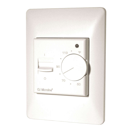
MTC is an electronic heating thermostat
designed to be installed in a standard single
gang electrical box with a minimum width of
2-1⁄4". Once installed, it requires no
maintenance.
An LED illuminates to indicate „call" for heating,
this also aids in system testing. An ON/OFF
selector switch on the front of the cover makes
system operation extremely simple.
PRODUCT LINE
With 16A relay switch, °F-scale
240V supply
MTC-1991-UFH
MTC-1999-UFH
with built-in air sensor
120V supply
MTC-2991-UFH
MTC-2999-UFH
with built-in air sensor
24V
MTC-3991-UFH
MTC-3999-UFH
with built-in air sensor
With 16A relay switch , °C-scale
240V supply
MTC-1991-UCH
MTC-1999-UCH
with built-in air sensor
120V supply
MTC-2991-UCH
MTC-2999-UCH
with built-in air sensor
24V supply
MTC-3991-UCH
MTC-3999-UCH
with built-in air sensor
APPROVALS (only 120/240V AC, 60 Hz)
MTC thermostats are UL and cUL Listed and
meet UL8730-1 and UL8730-2-9 standards for
temperature indicating and regulating
equipment.
CLASSIFICATION
The product is class II device (240V, 120V) and
a class III device (24V) according to UL 8730-1.
WARNING
The system may not be energized unless the
system is installed according to this
instruction and the installation meets all
applicable codes.
Warranty is void if not installated according to
this instruction and proper procedure.
TECHNICAL DATA
Power supply (model dependent)
.24, 120 and 240V AC ±10%, 50-60 Hz
Output relay, SPST (resistive load) . . . . . . . .16A
Built-in switch . . . . . . . . . . . . . . . . . .2 pole, 16A
Ambient operating
temperature . . . . . . . . . . . . . .32-122°F (0-50°C)
Scale limitation . . . . . . .minimum and maximum
Scale range . . . . . . . . . . . . .50-122°F (10-50°C)
Temperature setback . . . . . . . . . . .not available
On/Off differential . . . . . . . . . . . . . .0.7°F (0.4°C)
Enclosure . . . . . . . . . . . . . . . . . . . . . . . . . . .IP20
x
x
Dimensions (H
W
D) . . . . . . . . .
Environment and recycling
Please help us to protect the environment by
disposing of the packaging in accordance with
the national regulations for waste processing.
Recycling of obsolete appliances
FLOOR SENSOR INSTALLATION
(where applicable)
The sensor shall be mounted in a conduit which
should be sealed and placed as high as
possible in the concrete, etc. The sensor is UL
recognised and CSA certified. The sensor wiring
may be extended up to 150' (50 m) using 18
gauge wire and the wiring resistance shall not
with floor sensor
exceed 20 ohms. Sensor wires must be kept in
a separate conduit, away from all other wiring.
The sensor and wires must be protected from
damage during the installation. If shielded wire
with floor sensor
is used, it must not be grounded but connected
to terminal 6 on the thermostat.
with floor sensor
ERROR DETECTION
The MTC has built-in error detection which will
de-energize the heating circuit if the sensor is
damaged or if it detects an open or shorted
sensor circuit.
with floor sensor
CAUTION!
Disconnect all electrical power prior to
installing or servicing this unit.
with floor sensor
THERMOSTAT INSTALLATION (fig. 1-2)
1. Remove thermostat knob, noting the
position (A).
with floor sensor
2. Loosen screw to remove frame and cover
(B).
3. Attach wiring from the rear of the thermostat
according to the wiring diagram.
4. The thermostat is mounted in a standard
single gang electrical box with a minimum
width of 2-1/4". Please ensure that the
adapter plate is properly clipped on the
thermostat.
- re-install frame and cover
- re-install the knob in the proper position
TEMPERATURE SETTING/ADJUSTMENT
Adjust the temperature knob to the desired
room or floor temperature, if after a few days
you find the temperature to be different from the
setting, adjustment can be made as follows:
Measure the room temperature with
thermometer, remove the knob without rotating
it, then reposition the knob according to the
measured temperature on the scale and re-
install it.
MAXIMUM/MINIMUM TEMPERATURE
LIMITATIONS
Behind the knob there are red and blue locking
rings held in position by a screw. To set the
limitations, loosen the screw (C) and adjust the
red limit ring to the desired maximum, set the
blue ring to the desired minimum temperature,
then retighten the screw. The knob must be re-
installed exactly as it was removed.
4.5"x3.3"x2.0"
OJ ELECTRONICS A/S
(115x84x50 mm)
Stenager 13B · DK-6400 Sønderborg
Tel +45 73 12 13 14 · Fax +45 73 12 13 13
oj@ojelectronics.com · www.ojelectronics.com
Appliances with this label must not
be disposed off with the general
waste. They must be collected
separately and disposed off
according to local regulations.
© 2011 OJ Electronics A/S
© 2011 OJ Electronics A/S
Français
Type MTC avec capteur thermique ou
capteur de sol.
MTC est un thermostat électronique pour
installation de chauffage dont la conception
permet une installation directe dans un boîtier
électrique encastré standard avec un largeur de
min. 2-1⁄4" et ne demande aucun entretien une
fois installé.
Une diode électroluminescente "LED" s'allume
pour faire "appel" à la source de l'installation de
chauffage, celle-ci sert aussi en cas d'un
contrôle éventuel du système (test). Un
commutateur "Marche/Arrêt" placé sur la partie
frontale du couvercle permet une exploitation
du système d'une extrême simplicité.
LIGNE DE PRODUIT
Avec contact de relais de 16 A, pour °F
Alimentation 240V
MTC-1991-UFH
avec capteur de sol
MTC-1999-UFH
avec capteur incorporé
Alimentation 120V
MTC-2991-UFH
avec capteur de sol
MTC-2999-UFH
avec capteur incorporé
Alimentation 24V
MTC-3991-UFH
avec capteur de sol
MTC-3999-UFH
avec capteur incorporé
Avec contact de relais de 16 A, pour °C
Alimentation 240V
MTC-1991-UCH
avec capteur de sol
MTC-1999-UCH
avec capteur incorporé
Alimentation 120V
MTC-2991-UCH
avec capteur de sol
MTC-2999-UCH
avec capteur incorporé
Alimentation 24V
MTC-3991-UCH
avec capteur de sol
MTC-3999-UCH
avec capteur incorporé
APPROBATION
(Uniquement pour 120V CA et 240V CA, 60 Hz)
Les thermostats MTC sont sur les listes UL et
cUL et respectent les normes UL8730-1 et UL
8730-2-9 concernant l'indication de
températures et l'équipement de réglage.
CLASSIFICATION
Ce produit est un appareil de classe II (240V,
120V) et de classe III (24V) selon UL8730-1.
DANGER
Le système ne devra jamais être mis sous-
tension avant que celui-ci soit installé en
fonction des instructions d'installation et que
toutes les conditions nécessaires soient
comblées.
La garantie ne sera plus valable si les
instructions et procédures d'installation ne sont
pas respectées.
FICHE TECHNIQUE
Tension d'alimentation (selon le modèle)
. . . . . . . . . 24, 120 & 240V CA ±10%, 50-60 Hz
Relais sortie, SPST (charge résistive) . . . . . 16 A
Commutateur incorporé . . . . . . . bipolaire, 16 A
Température ambiante
d'exploitation . . . . . . . . . . . 32°-122°F (0°-50°C)
Advertisement

Related Manuals for OJ Electronics MTC-1991-UFH


Summary of Contents for OJ Electronics MTC-1991-UFH
- Page 1 Commutateur incorporé ..bipolaire, 16 A the national regulations for waste processing. Température ambiante d'exploitation ... 32°-122°F (0°-50°C) © 2011 OJ Electronics A/S © 2011 OJ Electronics A/S...
- Page 2 Con un termómetro, mida la de graduation et installez/réglez à nouveau. temperatura ambiente en la habitación, retire la perilla sin girarla, después vuelva a colocar la © 2011 OJ Electronics A/S © 2011 OJ Electronics A/S...
- Page 3 OJ ELECTRONICS A/S Stenager 13B · DK-6400 Sønderborg Tel. +45 73 12 13 14 · Fax +45 73 12 13 13 oj@ojelectronics.com · www.ojelectronics.com © 2011 OJ Electronics A/S © 2011 OJ Electronics A/S...
- Page 4 OJ ELECTRONICS A/S Stenager 13B · DK-6400 Sønderborg Tel. +45 73 12 13 14 · Fax +45 73 12 13 13 oj@ojelectronics.com · www.ojelectronics.com The trademark is registered and belongs to OJ Electronics A/S · © 2011 OJ Electronics A/S...