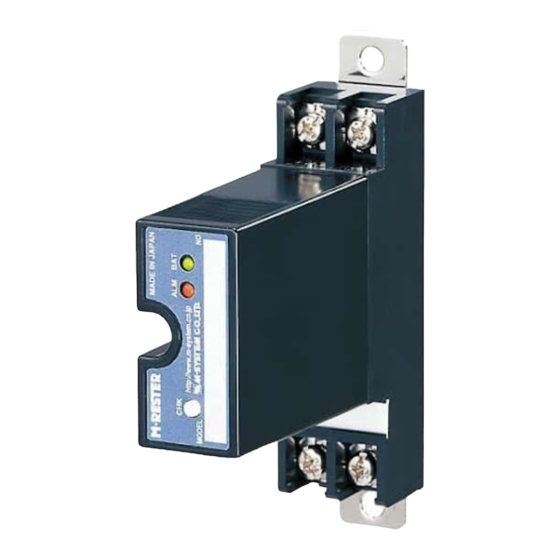
Table of Contents
Advertisement
Quick Links
INSTRUCTION MANUAL
LIGHTNING SURGE PROTECTOR FOR
RTD USE
BEFORE USE ....
Thank you for choosing M-System. Before use, please check
contents of the package you received as outlined below.
If you have any problems or questions with the product,
please contact M-System's Sales Office or representatives.
■ PACKAGE INCLUDES:
Surge protector ....................................................................(1)
■ MODEL NO.
Confirm Model No. marking on the product to be exactly
what you ordered.
■ INSTRUCTION MANUAL
This manual describes necessary points of caution when
you use this product, including installation, connection and
basic maintenance procedures.
When using this product in potentially explosive atmos-
phere or hazardous (classified) location, you have to follow
the safety procedure to install it. Please refer to "SAFE IN-
STALLATION MANUAL" for each type of certification.
LIMITATION APPLICABLE TO M-RESTER
The M-RESTER will protect electronics equipment from
damage caused by lightning by absorbing most of the
surge voltages.
However, M-RESTER may not be effective against cer-
tain extremely high voltages caused by a direct or almost
direct hit by lightning.
M-RESTER must be installed according to this installa-
tion / instruction manual.
Table 1. Specifications
MODEL NO.
Max. continuous operating voltage (Uc)
Voltage protection level (Up)
@4kV (1.2 / 50 µs)
Leakage current @Uc
Response time
Max. discharge current (Imax)
Nominal current (I
)
N
Internal series resistance
SEN TRONIC
(ultra-slim)
GENERAL
■ FUNCTION & FEATURES
• High discharge current capacity 20 kA (8 / 20 µs), 1 kA
• Ultra-thin 7-mm-wide module can be mounted in high
• Excellent protection employing multi-stage SPD circuits
• DIN rail mounting and grounding
• Shield terminal provided
• Does not affect instrumentation signal when combined
■ SPECIFICATIONS
See Table 1.
MD7RB-FF
Line to Line
Line to Earth
Line to SHLD
SHLD to Earth
±160V
Line to Line
Line to Earth
Line to SHLD
±1200V
SHLD to Earth
±800V
Line to Line
Other sections
Line to Line
Other sections
056 222 38 18
mailbox@sentronic.com
AG
MODEL
(10 / 350 µs)
density
with a 3-wire RTD, thanks to the internal high accuracy
series resistors
MD7RB-FG
MD7RB-GF
±3V
±160V
±160V
short
±160V
±25V
±800V
±800V
short
±800V
≤5µA
≤5µA
≤4 nsec.
≤20 nsec.
20kA (8 / 20 µs), 1.0kA (10 / 350 µs)
100mA
5.12Ω ±0.3%, ±30 ppm/°C per line
www.sentronic.com
MD7RB
MD7RB-GG
±7.5V
±7.5V
short
±25V
±25V
short
EM-8054 Rev.3 P. 1 / 4
Advertisement
Table of Contents

Summary of Contents for M-system MD7RB-FF
- Page 1 RTD USE (ultra-slim) BEFORE USE ..GENERAL Thank you for choosing M-System. Before use, please check ■ FUNCTION & FEATURES contents of the package you received as outlined below. • High discharge current capacity 20 kA (8 / 20 µs), 1 kA If you have any problems or questions with the product, (10 / 350 µs)
- Page 2 MD7RB POINTS OF CAUTION INSTALLATION ■ ENVIRONMENT Mount the unit on a DIN rail. Once installed, do not move it to another DIN rail. • Indoor use. • When heavy dust or metal particles are present in the ■ MOUNTING THE UNIT ON A DIN RAIL air, install the unit inside proper housing with sufficient A) Hang the upper hook of the DIN rail mounting adaptor at ventilation.
- Page 3 MD7RB TERMINAL CONNECTION Connect the unit as in the diagram below. Be sure to ground the DIN rail on which the unit is mounted and cross-wire between the rail and FG terminal of the protected device as shown in Figure 1 in order to equalize the earth potential. When the unit is connected with a device which has no FG terminal, ground the surge protector only.
- Page 4 Ground only the surge protector when the protected device has no ground terminal. *4. Shield wiring method is an example. Proceed according to the system requirements. Table 2. WIRING INSTRUCTIONS MODEL MD7RB-FF MD7RB-FG MD7RB-GF MD7RB-GG TERM. 4 – 5 ■ EURO TERMINAL 5 – 6 Torque: 0.3 N·m...


Need help?
Do you have a question about the MD7RB-FF and is the answer not in the manual?
Questions and answers