Table of Contents
Advertisement
Quick Links
INSTRUCTION MANUAL
LIGHTNING SURGE PROTECTOR FOR STANDARD
SIGNAL LINE & PULSE USE
BEFORE USE ....
Thank you for choosing M-System. Before use, check the
contents of the package you received as outlined below.
If you have any problems or questions on the product, please
contact M-System's Sales Office or representatives.
PACKAGE INCLUDES:
Lightning surge protector .......................................... (1)
MODEL NO.
Check that model No. described on the specification label is
exactly what you ordered.
Installation / INSTRUCTION MANUAL
This manual describes necessary points of caution when you
use this product, including installation and basic mainte-
nance procedure.
When using this product in potentially explosive atmosphere
or hazardous (classified) location, you have to follow the
safety procedure to install it. Please refer to "SAFE INSTAL-
LATION MANUAL" for each type of certification.
LIMITATION APPLICABLE TO M-RESTER
The M-Rester will protect electronics equipment from dam-
age caused by lightning by absorbing most of the surge
voltages.
However, M-Rester may not be effective against certain
extremely high voltages caused by a direct or almost direct
hit by lightning.
M-Rester must be installed according to this installation /
instruction manual.
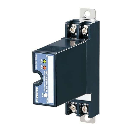
(conduit mount, weather-proof)
GENERAL
FUNCTION & FEATURES
• Designed specifically to protect 4 to 20mA DC and pulse
signal line including both 4-wire and 2-wire transmitters
• Direct mount in a wiring conduit of outdoor enclosures
• Absorbs surges only without affecting transmitted signals
SPECIFICATIONS
Discharge voltage 30V min.
(peak voltage)
Max. surge voltage* 40V max.
Leakage current
Max. line voltage
Response time
Capacitance
Discharge current
Max. load current
Internal series resist.
*The maximum voltage that could pass through M-RESTER.
Protected equipment must be able to withstand this voltage
for a very short time period.
POINTS OF CAUTION
GENERAL PRECAUTION
• Before you remove the unit or mount it, turn off the signal
input and the power supply to the connected devices for
safety.
ENVIRONMENT
• Do not install the M-RESTER where it is subjected to
continuous vibration. Do not apply physical impact to the M-
RESTER.
• Environmental temperature must be within -40 to +85°C
(-40 to +185°F) in order to ensure adequate life span and
operation.
INSULATION RESISTANCE TEST
• Before conducting an insulation test, remove the unit from
the protected signal line. Use a megger of 125V DC at the
maximum. If you use a higher-rated megger, the discharge
elements will start discharging, which will be detected falsely
as insulation failure.
AND ....
• We recommend that you keep spare M-RESTERs so that
you can replace them when necessary.
MD6x-24
MODEL
MD6x-65
BETWEEN LINES
MD6x-24
MD6x-65
70V min.
100V max.
≤5µA
≤5µA
@30V DC
@70V DC
30V DC
70V DC
≤4 nsec.
≤4 nsec.
≤2500 pF
≤2500 pF
@1kHz
@1kHz
10000A (8 / 20 µsec.)
100mA
approx. 22Ω including return
P. 1 / 6
EM-8283-A Rev.3
MD6x-24
MD6x-65
LINE TO GND
±160V min.
±650V max.
≤5µA
@±160V DC
–––
≤20 nsec.
≤100 pF
@1kHz
Advertisement
Table of Contents

Related Manuals for M-system MD6 24 Series


Summary of Contents for M-system MD6 24 Series
- Page 1 MD6x-65 (conduit mount, weather-proof) BEFORE USE ..GENERAL Thank you for choosing M-System. Before use, check the FUNCTION & FEATURES contents of the package you received as outlined below. • Designed specifically to protect 4 to 20mA DC and pulse...
- Page 2 MD6x-24 MD6x-65 COMPONENT IDENTIFICATION MD6T Set Screw Gasket * Terminal BLock Specification Label Leadwires Connecting Screw Body Functional Ground Cover *1. Not provided with 1/2 NPT. MD6N Gasket * Body Functional Ground Gasket * Leadwires (equipment side) Connecting Screw (equipment side) Specification Label Leadwires (calbe side) Connecting Screw (cable side)
- Page 3 MD6x-24 MD6x-65 EXTERNAL DIMENSIONS mm (inch) MD6T WITHOUT SAFETY APPROVAL G 1/2, 1/2 NPT or M20x1.5 G 1/2, 1/2 NPT or M20x1.5 69 (2.72) 35 (1.38) 79 (3.11) [91 (3.58)]** approx. 250 (9.8) WITH SAFETY APPROVAL G 1/2, 1/2 NPT or M20x1.5 G 1/2, 1/2 NPT or M20x1.5 69 (2.72) 41 (1.61)
- Page 4 MD6x-24 MD6x-65 MD6P G 1/2, 1/2 NPT or M20x1.5 27 (1.06) 52 (2.05) approx. 250 (9.8) 10 (.39) {17 (.67)}* [22 (.87)]** { } for M20x1.5 with CENECEC (ATEX) flameproof approval **[ ] for 1/2 NPT INSTALLATION • Confirm that the wiring conduit’s thread size of the protected device matches the connecting screw’s thread size of the unit. •...
- Page 5 MD6x-24 MD6x-65 MD6T CONNECTION DIAGRAM & GROUNDING Field Central Station (Protected Equipment Enclosure) MD6T-24 / MD6T-65 MDP-24-1 Protected Equipment MDP-65-1 Current Loop Supply yellow From Field Cable blue – – S– P– – To Central Station green (Protected Equiment) MD6N CONNECTION DIAGRAM & GROUNDING Field Central Station (Protected Equipment Enclosure)
- Page 6 M-System's option, the repair, replacement or refund of the purchase price of any M-System M-Rester which is defective under the terms of this warranty. To submit a claim under this warranty, the purchaser must return, at its expense, the defective M-System M-Rester to the below address together with a copy of its original sales invoice.
Need help?
Do you have a question about the MD6 24 Series and is the answer not in the manual?
Questions and answers