Table of Contents
Advertisement
Available languages
Available languages
Quick Links
Advertisement
Chapters
Table of Contents

Related Manuals for Genmitsu Jinsoku LC-50 Plus


Summary of Contents for Genmitsu Jinsoku LC-50 Plus
- Page 1 Genmitsu 取 扱 説 明 書 Jinsoku LC-50 Plus Laser Engraver & Cutter English 01 - 41 Jinsoku LC-50 Plus Lasergravier-/ und Schneidmaschin 日 本 語 43 - 85 Jinsoku LC-50 Plus レーザー彫刻カッター Deutsch 87 - 127 V1.0 Oct. 2022...
-
Page 2: Table Of Contents
Contents Welcome Safety Guidelines Product Structure and Accessories Packing List Product Parameters Assembly Guide Wiring Laser Focusing Installation of Raised Feet Function Introduction Resources Download and Driver Installation Software Installation... -
Page 3: Welcome
Welcome Thank you for purchasing the Jinsoku LC-50 Plus Laser Engraver & Cutter from SainSmart. Included in your package will be a USB Drive, that contains: ● Manuals ● Windows USB Driver ● Software LaserGRBL ● Sample Files Help and support are normally available from our Facebook Group. (SainSmart Genmitsu CNC Users Group, https://www.facebook.com/groups/SainSmart.GenmitsuCNC) -
Page 4: Safety Guidelines
Safety Guidelines Always exercise safety and caution when working with laser marking systems. Consider the listed recommendations to minimize risk: You must be at least 13 years old to operate the laser engraver. Direct exposure to the laser beam can cause severe burns and eye damage. Ensure that you are wearing proper laser safety goggles when working in the vicinity of the laser equipment. -
Page 5: Product Structure And Accessories
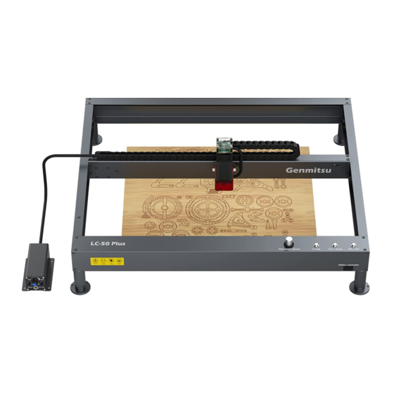
Product Structure and Accessories Top View Front View Rear Module Laser Head Module Right Module Left Module X-axis Module Offline Controller Focusing Tool E-stop Button Test Fire / Back to Home Button Power Button Front Module Right View Rear View USB Port for PC DC Power Jack... -
Page 6: Packing List
Packing List Front Module Left Module Right Module X-axis Module Linear Rod (4) Raised Rear Module (4) Support Foot Assembly Foot, 40mm (4) Support (3) M3*14mm 10W Laser Module (25) M4*10mm Screw Foot Holder Screw (2) M3*22mm (5) M3*6mm Screw (5) M4*8mm Screw (15) Cable Tie Screw... - Page 7 Packing List Allen Wrench USB Drive (2) Limit Switch User Manual 2mm,2.5mm,3mm Power Adapter Power Adapter Air Pump Power Supply Cable (US) Cable (EU) USB Data Cable Laser Safety Goggles 40mm Focusing Tool Coupling...
-
Page 8: Product Parameters
Product Parameters Model Name LC-50 Plus Work Area 19.68" x 15.75" x 2.83" (500x 400 x 72 mm) Control Board Compatibility GRBL Laser Power Driver Chip TB67S109 Control Board 32-Bit Max Speed 20000 mm/min Limit Switch XY Axis Software LaserGRBL/LightBurn Frame Material All Aluminum Linear Guide... -
Page 9: Assembly Guide
Assembly Guide STEP 1: Install the Support Feet to Front Module Flip the front module upside down and locate the pre-drilled holes. Install the support feet on each corner through the allen wrench. M4*8mm Screw M4*8mm Screw Front Module Support Foot Support Foot... - Page 10 Assembly Guide STEP 2: Install the Support Feet Holder to Support Feet Screw the support feet holder into support feet and tighten them. Support Feet Holder Support Feet Holder Front Module Support Foot Support Foot...
- Page 11 Assembly Guide STEP 3: Install the Support Feet to Rear Module Flip the rear module upside down and locate the pre-drilled holes. Install the support feet on each corner with the included allen wrench. M4*8mm Screw M4*8mm Screw Rear Module Support Foot Support Foot...
- Page 12 Assembly Guide STEP 4: Install the Support Feet Holder to Support Feet Screw the support feet holder into support feet and tighten them. Support Feet Holder Support Feet Holder Rear Module Support Foot Support Foot...
- Page 13 Assembly Guide STEP 5: Y-axis Left Module Assembly 1. Place the front module on a flat table as shown. 2. Align the Y-axis left module with the front module, then push the two modules fit closely together. Left Module Front Module Push 3.
- Page 14 Assembly Guide STEP 6: Y-axis Right Module Assembly 1. Align the Y-axis right module with the front module, then push the two modules fit closely together. Right Module Front Module Push 2. Put the M4*10mm screws into the screw holes and tighten them with the included 4mm Allen wrench. (Pay attention to the priority of assembling the front-end screws, and then assemble the top-end screws) (4) M4*10mm Screws Right Module...
- Page 15 Assembly Guide STEP 7: Rear Module Assembly 1. Align the rear module with the Y-axis left module and the Y-axis right module respectively as shown, and then push them closely to fit with the rear module. Rear Module Push Push 2.
- Page 16 Assembly Guide STEP 8: Linear Rod Assembly 1. Push the coupling as shown, insert the linear rod into the coupling, and the linear rod will protrude from the coupling. Push Optical Shaft Coupling 2. Insert the linear rod assembly through the (2) M4*6mm Screws timing belt as shown, then insert the linear rod into the bearing hole and push it to the...
- Page 17 Assembly Guide 5. Check if the timing belt position is as shown in the diagram. It must be between the timing Belt slot, bearing slot and idler slot. Bearing Slot Idler Pulley Slot Timing Belt Pulley Slot...
- Page 18 Assembly Guide STEP 9: X-axis Module Assembly 1. The X-axis module is placed above the both sliders on the Y-axis as shown in the diagram, and then the X-axis is dropped vertically. X-axis Module Slider Slider 2. Take four M4*10mm screws as shown to fix the left and right module respectively with the end of the X-axis module.
- Page 19 Assembly Guide STEP 10: Adjust the Tension of Timing Belt 1. Take M3*14mm screws as shown in the diagram, align the screw with the screwed hole at the right end of the rear module, then screw in and tighten it. (The timing belt tension has been initially adjusted at the factory, if you need to adjust, the side M5 screws can be adjusted by loosening.) 2.
- Page 20 Assembly Guide STEP 11: Fix Coupling 1. Push the X-axis module to the limit position as shown in the picture, and the push point is located in the middle of the X-axis module. 2. Tighten the M4*6mm screws on the coupling. 3.
- Page 21 Assembly Guide STEP 12: Fix Laser Module Place the laser module above the X-axis dovetail slot as shown, align the laser module dovetail block with the X-axis dovetail slot, then slide the laser module dovetail block into the X-axis dovetail slot, and tighten the side hand screw.
- Page 22 Assembly Guide STEP 13: Fix Drag Chain 1. Place the drag chain over the X-axis module as shown. 2. Fix the left end of the drag chain to the drag chain holder with M3*6mm screws. 3. Fix the right end of the drag chain to the X-axis module with M3*6mm screws. (2) M3*6mm Screw (2) M3*6mm Screw Drag Chain...
-
Page 23: Wiring
Wiring STEP 1: Wiring 1. Insert the Y-axis limit switch cable into the control board Y-axis limit cable interface according to the wire identification and the text of the control card interface, as shown in the diagram. 2. Insert the Y-axis motor cable into the Y-axis motor interface according to the wire identification as shown in the diagram. - Page 24 Wiring 3. As shown in the diagram, insert the X-axis limit switch cable into the X-axis limit cable interface according to the wire identification. 4. As shown in the diagram, insert the X-axis motor cable into the X-axis motor interface according to the wire identification.
- Page 25 Wiring 5. As shown in the diagram, connect the air tube with the air nozzle. 6. As shown in the diagram, according to the wire identification, insert the laser cable into the laser cable interface. Push Laser Cable Laser Cable Interface Air Tube Air Nozzle...
- Page 26 Wiring 7. Connect the air tube with the air tube interface as shown in the diagram. 8. Connect the air pump cable to the air pump cable interface. Air Tube Air Tube Interface Air Volume Adjustment Knob Air Pump Cable Interface Air Pump Cable...
- Page 27 Wiring 9. Secure the wire to the machine with a cable tie as shown. 10. After the wire is fixed, push the X-axis, Y-axis and Z-axis to move between the positive and negative limits to check whether the wire has pulled interference. 11.
- Page 28 Wiring STEP 2: Air Pump Power on Continuous Operation Wiring 1. Remove the air pump cable from the right air pump cable interface. 2. Cut the fixed wire ties, pull the air pump cable (can not pull the white part of the wire head), and then connect the air pump cable to the left air pump cable interface.
-
Page 29: Laser Focusing
Laser Focusing STEP 1: Adjust the Laser Module Focal Length 1. Loosen the 2 hood fixing screws by hand, and tighten the fixing screws when the hood is rotated to the state as shown. 2. Loosen the side hand screw. 3. -
Page 30: Installation Of Raised Feet
Installation of Raised Feet If you need to use the rotary axis for cylindrical material engraving, you can use the raised feet to raise the whole machine. 1. Remove the support feet holder from the support feet. 2. Screw the raised feet into the support feet as shown and tighten. 3. -
Page 31: Function Introduction
Function Introduction 40mm Focus Calibration Tool Test Fire / Back to Home Button (click to test fire, press to back to home) USB Data Cable E-stop Button Offline control Power Supply Power Button (To be purchased separately) 12V, 5A... -
Page 32: Resources Download And Driver Installation
Resources Download and Driver Installation Resources Download Method 1: Driver, software, sample picture and instructions can be found in the USB flash drive that comes with the machine. (Note: We recommend you to copy all files to your computer when you use it for the first time in case the flash drive gets lost.) Method 2: Download it from SainSmart Resources Center All files included in the flash drive can also be downloaded from SainSmart Resources Center: https://docs.sainsmart.com/lc50-plus or the following QR Code. - Page 33 Resources Download and Driver Installation Tips: To determine your machine's COM port: · Windows XP: Right click on "My Computer", select "Manage", select "Device Manager". · Windows 7: Click "Start" → Right click "Computer" → Select "Manage" → Select "Device Manager" from left pane.
-
Page 34: Software Installation
Software Installation Setup-LightBurn LightBurn You can use the laser engraving and cutting software Lightburn or LaserGBRL. Step 1: Install LightBurn and run the program. You can open this link or scan to get the LightBurn GCode License Key from SCAN TO SHOP SainSmart. - Page 35 Software Installation Step 5: Select the appropriate COM port. With a successful connection you will see text in the console window that says "Target buffer size found, ok" and show "Laser Ready". Work size could be change in Setting menu...
- Page 36 Software Installation Step 6: Click "Edit", select "Device Settings", check the Basic Settings,"Working Size", width=500mm, Height=400mm, "S-valueMax", S=10000.
- Page 37 Software Installation Engraving the Test File-Lightburn Step 1: File → Open File: Open G-CODE file or image format file. Step 2: Set the Origin Zero Position (Starting Point).
- Page 38 Software Installation Tip: Please zero the coordinates and adjust the focal length before engraving on the machine. Step 3: Double click the window "Spd/Pwr", set laser intensity (Svalue) and travel speed. The max power should be set 10%-100%, depending on materials they will require different speeds and percentage. Set the power scale to your lowest test power+10% to mimic what you want.
- Page 39 Software Installation Setup-LaserGRBL Step 1: Install Laser GRBL and run the program. Step 4: With a successful connection you will see green text in the console window that says “Grbl1.1f['$'for help]” Step 2: Connect your PC to the Control board with the included USB cable.
- Page 40 Software Installation Setting up Air-assist System Note: If you want to use the air-assist system with LaserGRBL, custom button should be added, you can download it via: https://lasergrbl.com/usage/custom-buttons/...
- Page 41 Software Installation Cutting the Test File-LaserGRBL Tip: Please adjust the focus before engraving Step 1: File → Open File: Open GCODE file or Step 3: Set the Speed and Values. Image format file, Here use “Letter A.JPG” as the Depending on Materials they will require different speeds test file.
-
Page 42: Faq
I. Unable to power on the machine. Ensure all outlets, switches, and power cables are plugged in and powered up properly. Try a different power source or cable if necessary. II. Unable to connect to computers. 1. USB cable not connected: Please make sure the data cable is correctly plugged. On some PCs, the front USB port is not receiving enough power for the engraving machine. - Page 43 3. Image Quality: If the image you imported has very light colors and fine lines, it will also affect the engraving quality. 4. Workpiece Position: The laser module has a fixed focal length, which means the workpiece should be placed on a flat surface and make sure it is in parallel to the machine, or poor engraving result.
- Page 44 Inhalt Elektro-undElektronikgeräte Willkommen Warnhinweise Bestandteile und Zubehör Lieferumfang Technische Daten Aufbau des Geräts Elektrischer Anschluss Fokussieren des Lasers Installation der Fußverlängerungen Funktionsbeschreibung Download und Treiberinstallation Software Installation...
-
Page 45: Elektro-Undelektronikgeräte
Elektro- und Elektronikgeräte Informationen für private Haushalte Das Elektro- und Elektronikgerätegesetz (ElektroG) enthält eine Vielzahl von Anforderungen an den Umgang mit Elektro- und Elektronikgeräten. Die wichtigsten sind hier zusammengestellt. 1. Getrennte Erfassung von Altgeräten Elektro- und Elektronikgeräte, die zu Abfall geworden sind, werden als Altgeräte bezeichnet. Besitzer von Altgeräten haben diese einer vom unsortierten Siedlungsabfall getrennten Erfassung zuzuführen. - Page 46 und Versandflächen für Elektro- und Elektronikgeräte mindestens 400 m² betragen oder die gesamten Lager- und Versandflächen mindestens 800 m² betragen. Vertreiber haben die Rücknahme grundsätzlich durch geeignete Rückgabemöglichkeiten in zumutbarer Entfernung zum jeweiligen Endnutzer zu gewährleisten. Die Möglichkeit der unentgeltlichen Rückgabe eines Altgerätes besteht bei rücknahmepflichtigen Vertreibern unter anderem dann, wenn ein neues gleichartiges Gerät, das im Wesentlichen die gleichen Funktionen erfüllt, an einen Endnutzer abgegeben wird.
-
Page 47: Willkommen
Willkommen Vielen Dank, dass Sie die Jinsoku LC-50 Plus Lasergravier-/ und Schneidmaschine von SainSmart gekauft haben. Im Lieferumfang ist ein USB-Stick enthalten. Auf diesem befinden sich: ● PDF Version des Benutzerhandbuchs ● Windows USB-Treiber ● GrbIControl/Candle Software für Windows ● Beispieldateien Hilfe und Unterstützung erhalten Sie am einfachsten in unserer Facebook-Gruppe. -
Page 48: Warnhinweise
Warnhinweise Gehen Sie bei der Arbeit mit Lasergraviersystemen stets mit Bedacht und Vorsicht vor. Beachten Sie die aufgeführten Empfehlungen, um mögliche Risiken zu minimieren: Sie müssen mindestens 13 Jahre alt sein, um den Lasergravierer zu bedienen. Direkter Kontakt mit dem Laserstrahl kann zu schweren Verbrennungen und Augenschäden führen. Stellen Sie sicher, dass Sie eine geeignete Laserschutzbrille tragen, wenn Sie in der Nähe des Lasergeräts arbeiten. -
Page 49: Bestandteile Und Zubehör
Bestandteile und Zubehör Ansicht von Vorne Ansicht von oben Hinteres Modul Laserkopf-Modul Rechtes Modul Linkes Modul X-Achsen Modul Fokussierungswerkzeug Offline Controller Notaus Knopf Einmal Drücken: Einschalten des Lasers auf niedriger Leistung Lange Drücken: Verfahren zum Startpunkt Vorderes Modul Netzschalter Ansicht von Rechts Ansicht von hinten USB-Port für PC DC-Stromanschluss... -
Page 50: Lieferumfang
Lieferumfang Vorderes Modul Linkes Modul Rechtes Modul X-Achsen Modul (4) Fußstütze, Hinteres Modul Leitspindel (4) Gummifuß 40mm (4) Gummi- (25) M4*10mm (3) M3*14mm 10W Laser Modul fußhalterung Schraube Schraube (2) M3*22mm (5) M3*6mm (5) M4*8mm (15) Kabelbinder Schraube Schraube Schraube... - Page 51 Lieferumfang Inbusschlüssel-Satz, USB-Stick (2) Endschalter Benutzerhandbuch 2mm; 2,5mm; 3mm Luftpumpe Netzkabel (US) Netzkabel (EU) Netzteil USB-A <-> USB-B 40mm Laser Sicherheits Brille Kupplung Fokussierwerkzeug Kabel...
-
Page 52: Technische Daten
Technische Daten Modell Name LC-50 Plus Gravurbereich 500mm x 400mm x 72 mm Kompatibilität der Steuereinheit GRBL Laserleistung Schrittmotortreiber TB67S109 Steuerbaugruppe 32-Bit Maximale Geschwindigkeit 20000 mm/min Endschalter XY-Achse Software LaserGRBL/LightBurn Material der Konstruktion Aluminum Linear Schienen MGN12 CAM Software GrblControl(Candle) Bewegungssystem Linear Schienen+Riemenantrieb Netzteil... -
Page 53: Aufbau Des Geräts
Aufbau des Geräts Schritt 1: Montage der Fußstützen am Vorderen Modul Drehen Sie das Vordere Modul auf den Kopf und suchen Sie die vorgebohrten Löcher. Montieren Sie die Fußstützen an jeder Ecke mit Hilfe des Inbusschlüssels. M4*8mm Schraube M4*8mm Schraube Vorderes Modul Fußstütze Fußstütze... - Page 54 Aufbau des Geräts Schritt 2: Montage der Gummifußhalterungen an den Fußstützen Drehen Sie die Gummifußhalterungen handfest in die Fußstützen. Gummifußhalterung Gummifußhalterung Vorderes Modul Fußstütze Fußstütze...
- Page 55 Aufbau des Geräts Schritt 3: Montage der Fußstützen am Hinteren Modul Drehen Sie das Hintere Modul auf den Kopf und suchen Sie die vorgebohrten Löcher. Montieren Sie die Fußstützen an jeder Ecke mit Hilfe des Inbusschlüssels. M4*8mm Schraube M4*8mm Schraube Hinteres Modul Fußstütze Fußstütze...
- Page 56 Aufbau des Geräts Schritt 4: Montage der Gummifußhalterungen an den Fußstützen Drehen Sie die Gummifußhalterungen handfest in die Fußstützen. Gummifußhalterung Gummifußhalterung Vorderes Modul Fußstützen Fußstützen...
- Page 57 Aufbau des Geräts Schritt 5: Montage des linken Moduls 1. Legen Sie das vordere Modul wie abgebildet auf einen flachen Tisch. 2. Richten Sie das linke Modul am vorderen Modul aus und schieben Sie die beiden Module eng aneinander. Linkes Modul Vorderes Modul Schieben 3.
- Page 58 Aufbau des Geräts Schritt 6: Montage des rechten Moduls 1. Richten Sie das rechte Modul am vorderen Modul aus und schieben Sie die beiden Module eng aneinander. Right Module Front Module Push 2. Setzen Sie die M4*10mm Schrauben in die Schraublöcher und ziehen Sie diese mit dem mitgelieferten 4mm Inbusschlüssel fest.
- Page 59 Aufbau des Geräts Schritt 7: Montage des hinteren Moduls 1. Richten Sie das hintere Modul wie abgebildet auf das linke und das rechte Modul aus, und schieben Sie diese dann dicht an das hintere Modul heran. Schieben Schieben Hinteres Modul 2.
- Page 60 Aufbau des Geräts Schritt 7: Montage der Leitspindel 1. Schieben Sie die Kupplung wie abgebildet auf die Leitspindel, sodass die Leitspindel aus der Kupplung herausragt. Schieben Leitspindel Kupplung 2. Positionieren Sie die (2) M4*6mm Schrauben Leitspindelbaugruppe wie gezeigt innerhalb des Zahnriemens. Schieben Sie dann die (2) M4*6mm Linearstange durch die Lagerbohrung in die Schrauben...
- Page 61 Aufbau des Geräts 5. Prüfen Sie, ob die Position des Zahnriemens wie in der Abbildung gezeigt ist. Er muss sich zwischen dem Zahnriemenschlitz, dem Lagerschlitz und dem Umlenkrollenschlitz befinden. Lagerschlitz Umlenkrollenschlitz Zahnriemenschlitz...
- Page 62 Aufbau des Geräts Schritt 9: Montage des X-Achsen Moduls 1. Platzieren Sie das X-Achsen Modul, wie in der Abbildung gezeigt, über den beiden Schlitten der Linearführung und Schieben es anschließend auf diese. X-Achsen Modul Schlitten Schlitten 2. Setzen Sie die M4*10mm Schrauben in die Schraublöcher und ziehen Sie diese mit dem mitgelieferten 4mm Inbusschlüssel fest.
- Page 63 Aufbau des Geräts Schritt 10: Einstellen der Zahnriemenspannung 1. Richten Sie die M3*14mm Schrauben wie in der Abbildung gezeigt, mit dem Schraubenloch am rechten Ende des hinteren Moduls aus, dann drehen Sie die Schrauben ein und ziehen sie fest. (Die Zahnriemenspannung ist werkseitig eingestellt, wenn Sie diese anpassen müssen, können die seitlichen M5-Schrauben entsprechend gelöst werden.) M3*14mm Screw...
- Page 64 Aufbau des Geräts Schritt 11: Fixieren der Kupplung 1. Schieben Sie das X-Achsenmodul in die Endposition, wie in der Abbildung gezeigt, wobei sich der Druckpunkt in der Mitte des X-Achsenmoduls befindet. 2. ziehen Sie die M4*6mm Schrauben an der Kupplung fest. Schieben Sie das X-Achsenmodul hin und her und beobachten Sie, ob es sich leichtgängig bewegen lässt.
- Page 65 Aufbau des Geräts Schritt 12: Montage des Lasermoduls Positionieren Sie das Lasermodul wie abgebildet über dem X-Achsenmodul und schieben es in den Schwanenschwanzschlitz. X-Achsenmodul Schwanenschwanzschlitz Lasermodul Handschraube Schwanenschwanzblock Schieben...
- Page 66 Aufbau des Geräts Schritt 13: Montage der Schleppkette 1. Legen Sie die Schleppkette wie abgebildet über das X-Achsenmodul. 2. Befestigen Sie das linke Ende der Schleppkette mit M3*6mm Schrauben am Schleppkettenhalter. 3. Befestigen Sie das rechte Ende der Schleppkette mit M3*6mm-Schrauben am X-Achsen-Modul. (2) M3*6mm Schraube (2) M3*6mm Schraube Schleppkette...
-
Page 67: Elektrischer Anschluss
Elektrischer Anschluss Schritt 1: Verkabelung 1. Stecken Sie das Kabel des Endschalters der Y-Achse in die Schnittstelle der Steuerbaugruppe entsprechend der Aderkennzeichnung und dem Text der Schnittstelle der Steuerbaugruppe, wie in der Abbildung gezeigt. 2. Stecken Sie das Kabel des Y-Achsenmotors in die Schnittstelle der Steuerbaugruppe entsprechend der Aderkennzeichnung und dem Text der Schnittstelle der Steuerbaugruppe, wie in der Abbildung gezeigt. - Page 68 Elektrischer Anschluss 3. Stecken Sie das Kabel des Endschalters der X-Achse in die Schnittstelle der Steuerbaugruppe entsprechend der Aderkennzeichnung und dem Text der Schnittstelle der Steuerbaugruppe, wie in der Abbildung gezeigt. 4. Stecken Sie das Kabel des X-Achsenmotors in die Schnittstelle der Steuerbaugruppe entsprechend der Aderkennzeichnung und dem Text der Schnittstelle der Steuerbaugruppe, wie in der Abbildung gezeigt.
- Page 69 Elektrischer Anschluss 5. Verbinden Sie den Luftschlauch wie in der Abbildung gezeigt mit der Luftdüse. 6. Stecken Sie das Kabel des Lasermoduls wie in der Abbildung gezeigt entsprechend der Kabelkennzeichnung in die Laser Schnittstelle. Push Kabel des Lasermoduls Laser Schnittstelle Luftschlauch Luftdüse...
- Page 70 Elektrischer Anschluss 7. Verbinden Sie den Luftschlauch mit der Luftausgang der Pumpe wie in der Abbildung gezeigt. 8. Verbinden Sie das Kabel der Luftpumpe mit der Schnittstelle für die Luftpumpe. Luftschlauch Luftschlauch Schnittstelle Einstellknoopf für die Luftmenge Luftpumpe Schnittstelle Kabel der Luftpumpe...
- Page 71 Elektrischer Anschluss 9. Befestigen Sie das Kabel wie abgebildet mit einem Kabelbinder an der Maschine. 10. Nachdem der Draht befestigt ist, schieben Sie die X-Achse, Y-Achse und Z-Achse zwischen den positiven und negativen Grenzwerten, um zu prüfen, ob der Draht die Bewegung behindert. 11.
- Page 72 Elektrischer Anschluss Schritt 2: Verkabelung der Luftpumpe bei Dauerbetrieb 1. Entfernen Sie das Kabeld er Luftpumpe von der rechten Luftpumpenschnittstelle. 2. Schneiden Sie die Kabelbinder durch, ziehen Sie das Luftpumpenkabel heraus (der weiße Teil des Kabelkopfes darf nicht gezogen werden) und schließen Sie das Luftpumpenkabel an die linke Luftpumpenschnittstelle an. Kabel der Luftpumpe Kabel der Luftpumpe...
-
Page 73: Fokussieren Des Lasers
Fokussieren des Lasers Schritt 1: Einstellen der Brennweite des Lasermoduls 1. Lösen Sie die 2 Fixierungsschrauben der Haube von Hand und ziehen Sie anschließend wieder fest, wenn die Haube in die abgebildete Position gedreht wurde. 2. Lösen Sie die seitliche Handschraube. 3. -
Page 74: Installation Der Fußverlängerungen
Installation der Fußverlängerungen Wenn Sie die Drehachse für die Gravur von zylindrischem Material verwenden müssen, können Sie die angehobenen Füße verwenden, um die gesamte Maschine anzuheben. 1. Entfernen Sie die Gummifußhalterung von den Fußstützen. 2. Schrauben Sie die Fußverlängerung wie gezeigt in die Fußstützen und ziehen Sie sie hand fest. 3. -
Page 75: Funktionsbeschreibung
Funktionsbeschreibung 40mm Fokussierungswerkzeug Einmal Drücken: Einschalten des Lasers auf niedriger Leistung Lange Drücken: Verfahren zum Startpunkt USB-A <-> USB-B Kabel Notaus Knopf Offline controller Netzschalter (Zusätzlich erhältlich) Netzteil 12V 5A... -
Page 76: Download Und Treiberinstallation
Download und Treiberinstallation Download Methode 1: Treiber, Software, Beispielbild und Anweisungen befinden sich auf dem USB-Stick, der mit dem Gerät geliefert wird. (Hinweis: Wir empfehlen Ihnen, alle Dateien auf Ihren Computer zu kopieren, wenn Sie das Gerät zum ersten Mal benutzen, falls der USB-Stick verloren geht). - Page 77 Download und Treiberinstallation So bestimmen Sie den COM-Anschluss Ihres Geräts: Windows XP: Klicken Sie mit der rechten Maustaste auf "Arbeitsplatz", wählen Sie anschließend "Verwalten", wählen danach "Geräte-Manager". Windows 7: Klicken Sie auf „Start“ → Klicken Sie mit der rechten Maustaste auf „Computer“ → Wählen Sie „Verwalten“...
-
Page 78: Software Installation
Software Installation Setup-LightBurn LightBurn Sie können folgen Link öffnen Schritt 1: Installieren Sie LightBurn und führen Sie oder scannen, um den LightBurn SCAN TO SHOP das Programm aus. GCode-Lizenzschlüssel von SainSmart zu erwerben. https://www.sainsmart.com/produ cts/lightburn-gcode-license-key Schritt 2: Schließen Sie Ihren PC mit dem mitgelieferten USB-Kabel an die Steuerbaugruppe an. - Page 79 Software Installation Schritt 5: Wählen Sie den entsprechenden COM-Anschluss. Bei erfolgreicher Verbindung sehen Sie im Konsolenfenster den Text "Target buffer size found, ok" und die Anzeige "Laser Ready". Work size could be change in Setting menu...
- Page 80 Software Installation Schritt 6: Klicken Sie auf "Edit", wählen Sie "Settings", wählen Sie die Grundeinstellungen, "Workingsize", width=600mm, Height=600mm, "S-valueMax", S=10000.
- Page 81 Software Installation Gravieren der Testdaei - Lightburn Schritt 1: File → Open File: Öffnen Sie eine G-CODE-Datei oder eine Datei im Bildformat. Schritt 2: Legen Sie die Nullposition des Ursprungs (Startpunkt) fest.
- Page 82 Software Installation Hinweis: Bitte setzen Sie die Koordinaten auf Null und stellen Sie die Brennweite ein, bevor Sie mit der Maschine gravieren Schritt 3: Doppelklicken Sie auf das Fenster "Spd/Pwr", stellen Sie die Laserintensität (Svalue) und die Fahrgeschwindigkeit ein. Die maximale Leistung sollte zwischen 10% und 100% eingestellt werden, je nach Material sind unterschiedliche Geschwindigkeiten und Prozentsätze erforderlich.
- Page 83 Software Installation Setup-LaserGRBL Schritt 1: Installieren Sie LaserGRBL und führen Sie das Schritt 4: Bei erfolgreicher Verbindung sehen Sie im Konsolenfenster einen grünen Programm aus. Text mit der Aufschrift "Grbl1.1f['$'for help]". Schritt 2: Verbinden Sie Ihren PC über das mitgelieferte USB-Kabel mit der Steuerbaugruppe.
- Page 84 Software Installation Einrichten des Luftunterstützungssystems Hinweis: Wenn Sie das Luftunterstützungssystem mit LaserGRBL verwenden möchten, muss eine benutzerdefinierte Schaltfläche hinzugefügt werden. Sie können diese unter https://lasergrbl.com/usage/custom-buttons/...
- Page 85 Software Installation Schneiden der Testdatei-LaserGRBL Tipp: Bitte stellen Sie den Fokus vor der Gravur ein Schritt 1: File → Open File: Schriit 3: Stellen Sie die Geschwindigkeit und die Werte ein. Öffnen Sie eine G-CODE-Datei oder eine Je nach Material werden unterschiedliche Geschwindigkeiten Datei im Bildformat, verwenden Sie hier und Werte.
-
Page 86: Faq
I. Das Gerät lässt sich nicht einschalten. Vergewissern Sie sich, dass alle Steckdosen, Schalter und Stromkabel richtig angeschlossen und eingeschaltet sind. Versuchen Sie ggf. eine andere Stromquelle oder ein anderes Kabel. II. Es kann keine Verbindung zu Computern hergestellt werden. 1. - Page 87 2. Graviergeschwindigkeit: Wenn Sie die Graviergeschwindigkeit zu schnell einstellen, hat der Laser nicht genügend Zeit, um Ihr Werkstück zu gravieren. Bitte passen Sie Ihre Gravureinstellungen an und führen Sie die Gravur erneut durch. 3. Bildqualität: Wenn das von Ihnen importierte Bild sehr helle Farben und feine Linien aufweist, beeinträchtigt dies auch die Gravurqualität.
- Page 88 目次 ようこそ! 安全ガイドライン 製品構造および付属品 付属品 仕様 組立ガイド 配線処理 レーザー焦点調整 継ぎ脚の取り付け 機能紹介 リソースダウンロードおよびドライバーインストール ソフトウェアインストール...
- Page 89 ようこそ! Jinsoku LC-50 Plus レーザー彫刻カッターをお買い上げいただき、誠にありがとうございます。 パッケージに同梱されているUSBメモリーには、以下の内容が含まれています。 PDF版マニュアル Windows USB ドライバー LaserGRBLソフトウェア サンプルファイル ヘルプとサポートは、下記Facebookグループからも利用できます。(SainSmart Genmitsu CNC Usersグループ, https://www.facebook.com/groups/SainSmart.GenmitsuCNC) 保証および技術サポートにつきましては、support@sainsmart.com までお問い合わせください。 SainSmartオンラインリソースセンターにアクセスし、CNCドライバーとソフトウェアをインストールしてく ださい。 https://docs.sainsmart.com/lc50-plus...
- Page 90 安全ガイドライン レーザーマーキングシステムで作業するときは、常に安全の確保と注意を払ってください。 リスクを最小限に抑えるため、以下の項目を考慮してください。 本機の操作は年齢13歳以上に制限します。 レーザー光を直接人体に当たると、重度の火傷や目の損傷を引き起こします。レーザー機器の近くで 作業するときは、適切な安全ゴーグルを着用していることを確認してください。 レーザーの焦点を合わせるときは、最低出力設定でのみ行ってください。 レーザーの使用は予期せぬ火災の原因となります。お近くに消火器を常備してください。 稼働中のレーザーを絶対に放置しないでください。 彫刻/カッティング加工中に発生するガスや煙は、人体に有害である可能性があるため、室内から排出する 必要があります。屋外への排出換気システムがあることを確認してください。 レーザーが照射される加工領域が、金属または不燃性であることを確認してください。 レーザーを操作している部屋または区画に、適切な標識が貼られていることを確認し、稼働中の作業エリア に第三者が不用意に足を踏み入れないようにしてください。 レーザー機器の清掃、メンテナンス、修理を行う際は、必ず電源を切ってください。 彫刻加工中に発生する、明るく強い光を直視しないでください。目に深刻な損傷を与える可能性があります。 意図された目的以外にレーザーを使用しないでください。 SainSmartは、レーザーの使用または誤用について一切の責任を負いません。...
- Page 91 製品構造および付属品 上面ビュー 前面ビュー レーザーヘッド 後部モジュール モジュール 右側モジュール 左側モジュール X軸モジュール 焦点調整ツール オフラインコントローラー 緊急停止ボタン レーザーLow点灯/ ホーム位置移 電源ボタン 前部モジュール 右側面ビュー 後面ビュー PC接続用USBポート DC電源ジャック...
- Page 92 付属品 前部モジュール Y軸左モジュール Y軸右モジュール X軸モジュール 後部モジュール リニアロッドASSY (4) 支持脚 (4) 継ぎ脚, 40mm 10Wレーザー (4) 支持脚ホルダー (25) M4*10mmねじ (3) M3*14mm ねじ モジュール (2) M3*22mm ねじ (5) M3*6mm ねじ (5) M4*8mm ねじ (15) 結束バンド...
- Page 93 付属品 六角棒レンチ ユーザーマニ (2) リミットスイッチ USBメモリー 2mm,2.5mm,3mm ュアル 電源アダプタケ 電源アダプタ エアポンプ 電源アダプタ ーブル (US/JP) ケーブル(EU) 40mm焦点調整 レーザー安全めがね カップリング USBケーブル ツール...
- Page 94 仕様 モデル名 LC-50 Plus 作業領域 500 x 400 x 72 mm (19.68 x 15.75 x 2.83 inch) 制御ボード互換 GRBL レーザー出力 モータードライバー TB67S109 制御ボードCPU 32ビット 最大移動速度 20000 mm/分 リミットスイッチ X/Y軸 ソフトウェア LaserGRBL/LightBurn フレーム材質 アルミニウム リニアガイド MGN12 X,Y軸送りねじ ACME T10(10mm), Pitch:2mm, Lead:4mm Z軸送りねじ ACME T8(8mm), Pitch:2mm, Lead:4mm 制御ソフトウェア Grblcontrol (Candle) モーションシステム リニアガイド+ベルト駆動 電源アダプタ DC12V/5A 6.5kg 装置重量 継ぎ脚 40mm...
- Page 95 組立ガイド Step 1 : 支持脚を前部モジュールに取り付けます 前部モジュールを裏に返し、ねじ穴の位置を確認します。六角棒レンチを使用して、各コーナーに支持脚をね じで締め付けます。 M4*8mmねじ M4*8mmねじ 前部モジュール 支持脚 支持脚...
- Page 96 組立ガイド Step 2:支持脚ホルダーを支持脚に取り付けます 支持脚ホルダーを支持脚にねじ込みます。 支持脚ホルダー 支持脚ホルダー 前部モジュール 支持脚 支持脚...
- Page 97 組立ガイド Step 3:後部モジュールに支持脚を取り付けます 後部モジュールを裏に返し、ねじ穴の位置を確認します。六角棒レンチを使用して、各コーナーに支持脚をね じで締め付けます。 M4*8mmねじ M4*8mmねじ 後部モジュール 支持脚 支持脚...
- Page 98 組立ガイド Step 4:支持脚ホルダーを支持脚に取り付けます 支持脚ホルダーを支持脚にねじ込みます。 支持脚ホルダー 支持脚ホルダー 後部モジュール 支持脚 支持脚...
- Page 99 組立ガイド Step 5:Y軸左モジュールを組み立てます 1. 前部モジュールを平らなテーブルに置きます。 2. Y軸左モジュールを前部モジュールに合わせて押しつけ、密着させます。 Y軸左モジュール 前部モジュール 押しつけ密着 3. M4*10mmねじをねじ穴に入れ、付属の4mm六角棒レンチで締め付けます。(前面ねじを締め付ける順序に 注意し、上面ねじを締め付けます) (4) M4*10mmねじ Y軸左モジュール 前部モジュール...
- Page 100 組立ガイド Step 6:Y軸右モジュールを組み立てます 1. Y軸右モジュールを前部モジュールに合わせて押しつけ、密着させます。 Y軸右モジュール 前部モジュール 押しつけ密着 2. M4*10mmねじをねじ穴に入れ、付属の4mm六角棒レンチで締め付けます。(前面ねじを締め付ける順序に 注意し、上面ねじを締め付けます) (4) M4*10mmねじ Y軸右モジュール 前部モジュール...
- Page 101 組立ガイド Step 7:後部モジュールを組み立てます 1. 後部モジュールをY軸左モジュールとY軸右モジュールにそれぞれ合わせ、後部モジュールにぴったり合うよ うに押し込みます。 後部モジュール 押し込む 押し込む 2. M4*10mmねじをねじ穴に入れ、付属の4mm六角棒レンチで締め付けます。(前面ねじを締め付ける順序に 注意し、上面ねじを締め付けます) (4) M4*10mmねじ (4) M4*10mmねじ Y軸左モジュール Y軸右モジュール 後部モジュール...
- Page 102 組立ガイド Step 8:リニアロッドを組み立てます 1. リニアロッドにカップリングを押し込むと、リニアロッドがカップリングから突き抜けます。 押し込む リニアロッド カップリング 2. リニアロッドASSYにタイミングベルト (2) M4*6mmねじ を通します。リニアロッドをベアリング 穴に挿入し、限界位置まで (2) M4*6mmねじ 押し込みます。 3. モーター軸とカップリングを嵌め合わ せ、カップリング端面がモーター端面か ら5mmのところに合わせます。 ベアリング穴 4. カップリング左端をM4*6mmねじで締 モーター軸 め付け、右端のM4*6mmねじを仮止めし 押し込む ます。 リニアロッド カップリング タイミングベルト...
- Page 103 組立ガイド 5. タイミングベルト位置が下図の位置になっていることを確認してください。タイミングベルトスロット、ベ アリングスロット、アイドラースロットの間を通っている必要があります。 ベアリングスロット アイドラースロット タイミングベルト スロット...
- Page 104 組立ガイド Step 9:X軸モジュールを組み立てます 1. X軸モジュールをY軸両方のスライダー上に置き、X軸モジュールを垂直に落とし込みます。 X軸モジュール スライダー スライダー 2. M4*10mmねじを4本ずつ使用し、左右モジュールをそれぞれX軸モジュールの端で固定します。(前面ねじ を締め付ける順序に注意し、上面ねじを締め付けます) M4*10mmねじ...
- Page 105 組立ガイド Step 10:タイミングベルトの張り具合を調整します 1. M3*14mmねじを使用し、後部モジュール右端のねじ穴に合わせ、ねじを締め込みます。(タイミングベル トの張り具合は工場出荷時に調整済みです。調整が必要な場合は側面のM5ネジを緩めて調整してください。) 2. M3*14mmねじを使用し、後部モジュ M3*14mmねじ ール左端のねじ穴に合わせ、ねじを締め 込みます。タイミングベルトの締め付け が適度になったら締め込みを止め、左側 のM5ねじを締めます。(右側タイミン グベルトの締まり具合を参考にしてくだ さい。) M5ねじ M5ねじ 3. M3*22mmのねじを使用し、X軸モジ M5ねじ M3*22mmねじ ュール右端のねじ穴に合わせ、ねじを締 め込みます。(タイミングベルトの張り 具合は工場出荷時に調整済みです。調整 が必要な場合はサイドのM5ネジを 緩めて調整してください。)...
- Page 106 組立ガイド Step 11:カップリングを固定します 1. X軸モジュールを限界位置まで押し込みます。押し込む点はX軸モジュールの中央です。 2. カップリングのM4*6mmねじを締めます。 3. X軸モジュールを前後に押し、X軸モジュールがスムーズにスライドことを確認してください。 噛み込みがある場合は、タイミングベルトがきちんと締まっていることを確認してください。 タイミングベルトが合わない場合は、カップリングのM4×6mmねじを緩め、Step 10を参照 しながら調整し、上記手順1〜2の操作を繰り返してください。ここまでで調整は完了です。 (2) M4*6mmねじ X軸モジュール 押し込む...
- Page 107 組立ガイド Step 12:レーザーモジュールを固定します レーザーモジュールをX軸ダブテールスロットの上に置き、レーザーモジュールダブテールブロックをX軸ダ ブテールスロットに合わせ、レーザーモジュールダブテールブロックをX軸ダブテールスロットにスライドさ せ、側面の手締めねじを締め付けます。 X軸ダブテールスロット レーザーモジュールダブテールブロック 手締めねじ 押し込む...
- Page 108 組立ガイド Step 13:ドラッグチェーンを固定します 1.ドラッグチェーンをX軸モジュールの上に置きます。 2.ドラッグチェーンの左端をドラッグチェーンホルダーにM3*6mmねじで固定します。 3.ドラッグチェーンの右端をM3*6mmねじでX軸モジュールに固定します。 (2) M3*6mmねじ (2) M3*6mmねじ ドラッグチェーン X軸モジュール...
- Page 109 配線処理 Step 1:配線 1. Y軸リミットスイッチケーブルを制御ボードのY軸リミットスイッチI/Fに挿入します。ワイヤーIDと制御ボー ドI/Fの文字表示に従ってください。 2. Y軸モーターケーブルをY軸モーターI/Fに挿入します。 Y軸リミットスイッチI/F Y軸モーターケーブルI/F...
- Page 110 配線処理 3. ワイヤー識別に従って、X軸リミットスイッチケーブルをX軸リミットスイッチI/Fに挿入します。 4. ワイヤー識別に従って、X軸モーターケーブルをX軸モーターI/Fに挿入します。 X軸リミットス イッチI/F X軸リミットス イッチケーブル X軸モーターI/F X軸モーターケーブル (4ピン)
- Page 111 配線処理 5. エアチューブをエアノズルに接続します。 6. ワイヤー識別に従って、レーザーケーブルをレーザーI/Fに挿入します。 押し込む レーザーケーブル レーザーI/F エアチューブ エアノズル...
- Page 112 配線処理 7. エアチューブをエアチューブI/Fに接続します。 8. エアポンプケーブルをエアポンプI/Fに接続します。 エアチューブ エアチューブI/F エア圧力調整ノブ エアポンプI/F エアポンプケーブル...
- Page 113 配線処理 9. 結束バンドでワイヤーを装置に固定します。 10. ワイヤー固定後、X軸、Y軸、Z軸を左右上下各方向の限界まで手で移動させ、ワイヤーが干渉せず、突っ張 っていないことを確認します。 11. 結束バンドの余剰部分をカットします。 結束バンド 結束バンド...
- Page 114 配線処理 Step 2:エアポンプ電源の連続運転配線 1. 右側のエアポンプI/Fからエアポンプケーブルを取り外します。 2. 結束バンドをカットし、エアポンプケーブルを引き出して(ワイヤー先端の白いハウジング部分は引っ張ら ないようにしてください)、エアポンプケーブルを左側のエアポンプI/Fに接続します。 エアポンプ ケーブル エアポンプケーブル...
- Page 115 レーザー焦点調整 Step 1:レーザーモジュールの焦点距離を調整します 1. フード固定ねじ2本を手で緩め、フードを下図の状態まで起こした後、固定ねじを締め付けます。 2. 側面の手締めねじを緩めます。 3. レーザーモジュールヒートシンクの端面と彫刻材料の間に焦点調整ツールを配置し、焦点距離を40mmにす ばやく調整します。 4. 側面のねじを締めてレーザーモジュールを固定し、焦点距離がズレないようにします。 5. 焦点調整完了後、焦点調整ツールを取り外し、フードを下げます。 手締めねじ フード フード固定ねじ 40mm焦点 調整ツール...
- Page 116 継ぎ脚の取り付け 円筒形材料の彫刻に回転軸を使用する必要がある場合は、継ぎ脚を使用してマシン全体を持ち上げることがで きます。 1. 下図のように、支持脚から支持脚ホルダーを取り外します。 2. 継ぎ脚を支持脚にねじ込みます。 3. 支持脚ホルダーを継ぎ脚にねじ込みます。 支持脚 継ぎ脚 支持脚ホルダー...
- Page 117 機能紹介 40mm焦点 調整ツール レーザーLow点灯/ホーム位置移動ボタン (1回押し:Low点灯、長押し:ホーム位置へ移動) USBケーブル 緊急停止ボタン オフラインコント 電源アダプタDC ローラー (別売) 電源ボタン 12V/5A...
- Page 118 リソースダウンロードおよびドライバーインストール リソースダウンロード 方法その1:ドライバー、ソフトウェア、サンプル画像および手順は、装置に付属 の USBメモリーに保存されています。(注:USBメモリーの紛失に備え、全てのファ イルをコンピューターにコピーすることをお勧めします。) 方法その2:USBメモリーに保存されている全てのファイルは、SainSmartリソー スセンターからダウンロードできます。 SainSmartリソースセンターからダウンロード: https://docs.sainsmart.com/lc50-plus または以下のQRコードスキャン QRコードをスキャンしてソフトウェアとユーザーマニュアルをダウンロードしま しょう! USBドライバーのインストール...
- Page 119 リソースのダウンロードとドライバーのインストール ヒント:装置のCOMポートを確認するには〜 Windows XP:「マイコンピュータ」を右クリック →「マネージャー」→「デバイスマネージャー」を選択 Windows 7:「スタート」を右クリック →「コンピュータの管理」をクリック →「マネージャー」を選択し、 左ペインツリーから「デバイスマネージャー」を選択 Windows 8/10:「このPC」を右クリック →「マネージャー」を選択し、左ペインツリーから「デバイスマネ ージャー」を選択 画面左ツリーペインのポート(COM & LPT)を展開します。 お使いの装置はUSBシリアルポート (COMx) になります。「x」はCOMポート番号を表します。(例:COM12) USBシリアルポートが複数ある場合、それぞれを右クリックしてメーカーを確認してください。 装置は「CH340」になります。...
- Page 120 ソフトウェアインストール LightBurnのセットアップ LightBurn レ ー ザ ー 彫 刻 お よ び カ ッ ティン グ ソ フトウェア Lightburn または LaserGBRL を使用できます。 Step 1 : LightBurnをインストールしてプログラム を実行します。 下 の リンクを 開 くか ス キャンして、 SainSmartからLightBurn GCodeライセ SCAN TO SHOP ンスキーを取得できます。 https://www.sainsmart.com/product s/lightburn-gcode-license-key Step 2 : 付属のUSBケーブルを使用してPCを制 御ボードに接続します。...
- Page 121 ソフトウェアインストール Step 5 : 適切な COM ポートを選択します。 接続が成功すると、 コンソールウィンドウに 「Target buffer size found, ok」 のテキストと、 「 Laser Ready」 が表示されます。 Work size could be change in Setting menu...
- Page 122 ソフトウェアインストール Step 6 : メニューバー 「Edit」 をクリック → 「 Device Settings」 を選択 → Basic Settingsタブ → 「 Working Size」 Width=600mm、 Height=600mm 「S-valueMax」 S=10000 をチェックします。...
- Page 123 ソフトウェアインストール Lightburnテストファイルでの彫刻 Step 1 : メニューバー 「File」 をクリック→Open File: G-CODEファイルまたは画像形式ファイルを開きます。 Step 2 : 原点ゼロ位置 (始点) を設定します。...
- Page 124 ソフトウェアインストール ヒント 座標をゼロにし、機械で彫る前に焦点距離を調節してください Step 3: ウィンドウ「Spd/Pwr」をダブルクリックし、レーザー強度(Svalue)と移動速度を設定します。 最大出力は10〜100%に設定する必要があります。最適な速度と出力比は材料によって異なります。パワースケ ールを最小テスト出力+10%に設定して、必要な項目を模倣します。記録を採りながら、最適な出力と移動速度 を見つけてください。 Step 4:「Start」をクリックして彫刻を開始します。 詳細については、ドキュメント「LightBurnDocs」を参照してください。 メガネを着用してください ! レーザーを出力したまま放置しないでください。...
- Page 125 ソフトウェアインストール LaserGRBLのセットアップ Step 1:LaserGRBLをインストールしてプログラムを Step 4:接続が成功すると、コンソールウィ 実行します。 ンドウに「Grbl1.1f ['$' for help]」の緑色テキ ストが表示されます。 Step 2:付属のUSBケーブルを使用してPCを制御ボー ドに接続します。 Step 3:適切なCOMポートを選択し、Plug/Lightning アイコンをクリックして接続します。...
- Page 126 ソフトウェアインストール エアアシストシステムのセットアップ 注:LaserGRBLでエアアシストシステムを使用する場合は、カスタムボタンを追加する必要があります。 https://lasergrbl.com/usage/custom-buttons/ からダウンロードできます。...
- Page 127 ソフトウェアのインストール LaserGRBLテストファイルでのカッティング ヒント 彫刻する前に焦点を調節してください Step 1:メニューバー「File」をクリッ Step 3:移動速度と値を設定します。 ク→ Open File 材料に応じて、必要な速度と数値が異なります。 G-CODEファイルまたは画像形式ファイ ルを開きます。ここでは「LetterA.JPG」 材料:2mm厚 をテストファイルとして使用します。 バスウッド多層板 Speed:300 mm/min S-Max:10000 Step 4:方向ボタンをクリックして装置を制御し、 加工開始点に移動後、「Set Zero Point」をクリック Step 2:変換ツールとして「Vectorize」 してください。その後、「Run Program」をクリッ を選択し、「Next」をクリックします。 クしてカッティングを開始します。...
- Page 128 I. Unable to power on the machine. Ensure all outlets, switches, and power cables are plugged in and powered up properly. Try a different power source or cable if necessary. II. Unable to connect to computers. 1. USB cable not connected: Please make sure the data cable is correctly plugged. On some PCs, the front USB port is not receiving enough power for the engraving machine. We recommend using the USB port at the back for a stable connection. 2. The driver is not correctly installed: Install the driver according to the instructions again. After the installation is done, your computer can recognize the machine as a serial port. You can find a serial COM port in the computer's device manager. 3. If both solutions above are not working, try unplugging the USB cable and power cord, turn off the machine for at least five seconds, then power it on and reconnect again. III. Machine gives no response when controlling via the mobile phone application. 1. The wrong machine is connected: If you have multiple machines in the workspace, please make sure you connect to the correct machine. 2. Compatibility Issue: Compatibility issues may occur when updating your phone to a new system version. Please don't hesitate to contact us with your system information if that happens. We will add support for it as soon as possible. IV. The engraving looks blurry or shadowed. 1. Focus: Most commonly, the laser was not correctly focused before starting the job. 2. Engraving Speed: If you set the engraving speed too fast, the laser will have insufficient time to engrave ...
- Page 129 3. Image Quality: If the image you imported has very light colors and fine lines, it will also affect the engraving quality. 4. Workpiece Position: The laser module has a fixed focal length, which means the workpiece should be placed on a flat surface and make sure it is in parallel to the machine, or poor engraving result. V. Unexpected stops when offline engraving. The engraving job has not been fully transferred. Re-connect the machine and transfer the engraving job again should solve the problem. VI. Inaccurate focus Read the "Focus" section in the User Manual carefully. Use the focusing tools provided with the machine to ...
- Page 130 Genmitsu Desktop CNC & Laser www.sainsmart.com support@sainsmart.com Vastmind LLC, 5892 Losee Rd Ste. 132, N. Las Vegas, NV 89081...
Need help?
Do you have a question about the Jinsoku LC-50 Plus and is the answer not in the manual?
Questions and answers