Advertisement
Quick Links
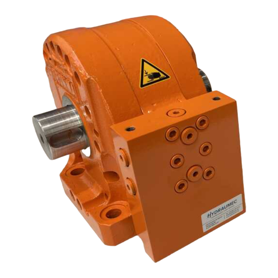
REPAIR MANUAL
ROTAC
Models:
SB-18 & SB-18.2
Bills of Material Part Numbers:
Micromatic # / Bromma Article #)
For further information contact:
MICROMATIC LLC
525 Berne St.
Berne, IN. 46711-1298
Ph 260 589 2136 Fax 260 589 8966
www.micromaticllc.com
RM – 26-10-7707
Rev. E
Page 1 of 39
Advertisement

Related Manuals for MICROMATIC ROTAC SB-18


Summary of Contents for MICROMATIC ROTAC SB-18
- Page 1 REPAIR MANUAL ROTAC Models: SB-18 & SB-18.2 Bills of Material Part Numbers: Micromatic # / Bromma Article #) For further information contact: MICROMATIC LLC 525 Berne St. Berne, IN. 46711-1298 Ph 260 589 2136 Fax 260 589 8966 www.micromaticllc.com RM –...
-
Page 2: Revision History
REVISION HISTORY REV. DATE DESCRIPTION REVISED / ADDED INSTRUCTIONS REGARDING ECO 11815 & 11864; 11DEC20 STINSON 1/2 - 13 TORQUE WAS 126 FT∙LBS, NOW 93 FT∙LBS REVISED/ADDED NEW ASSEMBLY TOOL KIT REGARDING ECO 02SEP21 LUTHMAN 12151; TOOL KIT PART NUMBER IS 26-97-0348 AND 26-97-0349;... - Page 3 INDEX OF SECTIONS INTRODUCTION DISASSEMBLY EVALUATION AND CORRECTIONS PREPARATION AND SEAL INSTALLATION ASSEMBLY WITH ASSEMBLY TOOLS ASSEMBLY WITHOUT ASSEMBLY TOOLS REFERENCE INFORMATION AND SPECIFICATIONS RM – 26-10-7707 Rev. E Page 3 of 39...
- Page 4 INTRODUCTION a) This document provides disassembly, inspection, assembly procedures and other relevant ® information for TWO generations of the SB-18 ROTAC Rotary Actuator model exclusively manufactured for BROMMA: Generation (GEN1) = SB-18-1V-DE-FLATS-FT and SB-18-1V-DE-KEY-FT (1) 26-10-7707 (BR1002277) shaft with flat ends (2) 26-10-7712 (BR1001276) shaft with round end and key slots ii) 2 Generation (GEN2) = SB-18.2-1V-DE-FLATS-FT and SB-18.2-1V-DE-KEY-FT...
- Page 5 ii) Shaft: (1) GEN2 Includes two (2) wear pad mounting slots on both sides of the vane. (a) Four (4) pads total in assembly for axial wear control. (2) The shaft with and without wear pads IS interchangeable between Gen1 and Gen2 models.
- Page 6 iv) A clean disassembly helps to identify that any material found inside the actuator is a result of wear, system contamination or damage. Ultimately, a more accurate evaluation of the actuator and operating system will be obtained. c) Mark parts: Before disassembly, the body, heads, and shaft should be marked in such a way as to aid in reassembly to return parts to their relative positions to avoid installing the shaft backwards.
- Page 7 (a) Removing material ‘smeared’ over the head bolts from high impact damage may be required to access and remove bolts. (b) An air hammer is recommended to drive out head dowels. (2) With the unit standing upright, strike end of shaft with plastic mallet or non-marring hammer and allow the shaft to push the opposite head/end off.
- Page 8 (4) Using a lower grit to polish the shaft can lead to shaft seal leaks. vi) Scoring or galling: (1) Check side faces of the shaft vane and side faces of the ‘A’ Diameter for scoring or galling. (a) Any scratches or galling of the part which are .010 in (0.25mm) or more deep requires replacement of the part.
- Page 9 j) Heads: Scoring on face of head MUST be repaired. ii) Journals: (1) Measure the diameter of the journal. (2) Refer to SECTION 7 at the end of this document for the specifications for maximum and minimum allowable diameters. (a) GEN1 heads require replacement if they are out of specification.
- Page 10 SEAL REPLACEMENT AND REASSEMBLY PREPARATION AND SEAL INSTALLATION a) Complete guidelines specified in the Evaluation and Corrections Section b) Parts should be re-cleaned if necessary. c) Ensure shaft journals at seal areas have not been scratched. d) A small pliable brush or non-lint towel with a high flash point solvent should be used to clean seal grooves, dowel holes, screw holes and other hard-to-get-at areas.
- Page 11 iv) GEN1 SB-18 Actuator: (1) Install Back-up Ring and O-ring (Item #25 & #24) into groove in head. (2) The Back-up Ring (Item #25) MUST be against outside wall of groove. (3) The O-ring (Item #24) installs into the same groove as Item #25 and MUST be on the inboard position and the groove.
- Page 12 (3) Use the ‘Kidney Bean’ method for deforming seals to fit into seal groove. (a) NOTE: If seal is kinked or damaged during installation it MUST be replaced to avoid external hydraulic fluid leaks. (4) The middle seal groove is not used; however, it is sized to accept the shaft seal parts in the event there is damage to one of the other seal glands.
- Page 13 j) Shoulder Seal Installation into Heads (x2): Ensure there are no dings or rounded edges on the shoulder seal pocket. ii) Place wavy spring(s) (Item #20) into pocket in head. (1) GEN1 has one (1) wavy spring / side (2) GEN2 has two (2) wavy springs / side iii) Install hub seal ring (Item #19) on top of wavy spring.
- Page 14 ASSEMBLY WITH ASSEMBLY TOOLS a) It is recommended that assembly tools be used to assemble the actuator. The assembly tools simplify assembly and significantly reduce the likelihood of damaging critical parts and features during the assembly process. b) A following Section below outlines a method to assemble the actuator without assembly tools. c) Assembly tool kit part numbers are identified in SECTION 7.
- Page 15 iv) If necessary, to temporarily ‘Hold’ parts in place, for example the dummy half keys, petroleum jelly can be used. (1) The ‘Earmuff’ portion of the vane seal cap is the ONLY portion of the seal which should ‘Stick’ in the corresponding vane groove. The rest of the vane seal cap should be free to float in the shaft groove.
- Page 16 Refer to Section 6 to assemble without assembly tools. ii) Place the assembly tool “Vane Seal Protector” on top of the body and align the two opposing dowel holes. (1) NOTE: MUST ensure the vane seal protector edge that has a ‘Tapered Lead In’ is on the TOP side and away from the Body.
- Page 17 k) Shaft Installation with Tools: Refer to Section 6 to assemble without assembly tools. ii) Flat End Shafts: (1) The hole in the flat of the shaft end MUST be oriented as shown. iii) Round End Shafts: (1) The key slots in the shaft MUST be oriented as shown.
- Page 18 (2) Verify fitment by evaluating dowel hole positions. (3) If the incorrect head is used, the mounting and dowel holes will not line up iii) Select Shaft Dependent Shaft Seal Protector Tools: (1) Flat End Shafts use the SK- 4391 Shaft Seal Protector. (2) Round End Shafts use the SK- 3229 Shaft Seal Protector.
- Page 19 (2) CAUTION: Excessive force, speed or tapping could dislodge seals. CAUTION PINCH HAZARD: Fingers can be pinched if head is allowed to fall uncontrolled onto the body. vii) While there is still a gap between the head and body, look inside to ensure shoulder seal parts and head seal have not shifted and become dislodged.
- Page 20 n) Head Dowels and Bolts Installation: Flip Actuator up such that it is setting on the mounting feet. ii) Install four (4) head dowels: (1) Head dowels are to be a slight press fit. DO NOT ream or enlarge dowel holes in actuator to make dowel installation easier.
- Page 21 ii) NOTE: GEN1 and GEN2 pressure relief cartridges are NOT interchangeable within the manifold blocks. GEN1 and GEN2 manifold assemblies ARE interchangeable between the actuator assemblies for each generation. iii) Pressure relief cartridges are pre-set from the factory and have tamper evident features. Do NOT attempt to adjust the pressure relief cartridges.
- Page 22 ASSEMBLY WITHOUT ASSEMBLY TOOLS a) It is recommended that assembly tools be used to assemble the actuator. Assembly tools simplify assembly and significantly reduce the likelihood of damaging critical parts and features during assembly. b) It is possible to assemble the actuator without assembly tools when extreme care and patience is taken and combined with the fabrication of simple wood supports.
- Page 23 f) Shoe Seal Install: Brush a light layer of assembly grease, petroleum jelly, into the grove in the body to aid on holding the parts in the groove. ii) Place the shoe seal and seal cushion into the shoe seal groove in the body and centered in the groove.
- Page 24 (c) Use a thin feeler gage or fingernails to evaluate this. (d) The vane and shoe seals WILL BE SLIGHTLY (0.01in (approx. ) / 0.25mm) ‘proud’ / sticking above the metal surface of the body as shown in figure image. (3) Adjust if necessary.
- Page 25 (2) Resistance may be encountered at various points while lowering the head, this is normal as the seals pass over edges on the shaft. LIGHTLY increase force to overcome resistance. (3) CAUTION: Excessive force, speed or tapping could dislodge seals. CAUTION PINCH HAZARD: Fingers can be pinched if head is allowed to fall uncontrolled onto the body.
- Page 26 k) Bearing Pad Installation #2: Brush assembly grease, petroleum jelly, into each of the grooves in the side of the shaft vane. ii) Take two (2) of the rectangular bronze (yellowish color) wear pads and place them into each of the two (2) grooves pressing the pads into the grease and slightly moving back and forth in the groove to promote sticking of the pads in the...
- Page 27 (1) In preparation to install dowel pins the assembly will require significant support to counteract the forces required to drive in the dowel pins that have an intentionally tight fit. (2) Refer to image for suggested options to support assembly using one or two of the support blocks fabricated previously.
- Page 28 m) Manifold Installation: Verify manifold O-ring cavities are clean and burr free. ii) Install the two (2) O-rings into cavities of the body. (1) Apply assembly grease (petroleum jelly) as an aid to retain O-rings in place. iii) With actuator and manifold sitting upright on its mounting flanges on an even and flat surface, slide manifold up to manifold boss on body.
- Page 29 REFERENCE INFORMATION AND SPECIFICATIONS a) IDENTIFICATION Assembly Part / Item Numbers; Generation 1 (GEN1) and Generation 2 (GEN2). (1) GEN2 actuators have .2 milled in the side face under the shaft and lower left corner of the manifold. RM – 26-10-7707 Rev.
- Page 30 b) ASSEMBLY TOOL KITS (2 TYPES) The assembly tools work on both GEN1 and GEN2 actuator assemblies. ii) FLAT SHAFT END ACTUATORS: 26-97-0348 - BILL OF MATERIAL (FLAT SHAFT ENDS) ITEM QTY. PART NUMBER DESCRIPTION SK-4312-1 BROMMA DUMMY HEAD PLATE 26-12-0141 SHCS 1/2"-13 X 1-1/4LG.
- Page 31 iii) ROUND SHAFT END ACTUATORS: 26-97-0349 - BILL OF MATERIAL (ROUND SHAFT ENDS) ITEM QTY. PART NUMBER DESCRIPTION SK-4312-1 BROMMA DUMMY HEAD PLATE 26-12-0141 SHCS 1/2"-13 X 1-1/4LG. SK-4318 PROTECTOR, VANE SEAL SK-5238-02 SHOE SEAL PROTECTOR, BROMMA A010152 PIN, SB, 18, DUMMY, DOWEL SK-3229 PROTECTOR, SHAFT SEAL SK-4399...
- Page 32 c) SEAL KITS The seal kits are different between GEN1 and GEN2 actuator assemblies. ii) Refer to insert with seal kits for additional information. SEAL KITS MODEL GENERATION KIT TYPE SEAL KIT NUMBER SB-18 GEN1 26-90-7707 ALL SEALS SB-18.2 GEN2 26-90-7747 SB-18 GEN1...
- Page 33 f) BREAK AWAY AND INTERNAL BYPASS Internal bypass performance is the same between GEN1 and GEN2 actuator assemblies. ii) Cycle actuator full stroke for one minute prior to taking any measurements. iii) INTERNAL BY-PASS LEAK: (1) The fluid is measured out the exhaust port of the actuator. (2) Pressure to be maintained listed for one (1) full minute before check is started.
-
Page 34: Troubleshooting
g) TROUBLESHOOTING TROUBLE POSSIBLE CAUSES REMEDIES Damaged Shaft Seal shaft Seal installed Replace shaft seals incorrectly. Disassemble, clean all debris and rust from shaft, shaft seal groove area, repair/polish as Contamination in seal area. necessary, install new seals. ... - Page 35 Defective Internal seals: o Shoe seal or shoe seal Inspect for damage, remedy, and replace cushion seals. o Vane seal or vane seal cushion Defective Hub/Shoulder Seal: Replace hub seal - Ensure tight fit to round o Hub seal pinched at pocket in head.
- Page 36 h) 26-10-7707 - GEN1 – SB-18 - EXPLODED VIEW OF ASSEMBLY 26-10-7707 - GEN1 – SB-18 - BILL OF MATERIAL ITEM QTY. PART NUMBER DESCRIPTION 26-01-2599 BODY SB-18 26-02-3916 HEAD-SB-18 RIGHT HAND 26-02-3917 HEAD-SB-18 LEFT HAND 26-05-4520 SHAFT WITH FLATS -SB-18 26-09-2752 SHOE, SEAL CAP 26-09-2753...
- Page 37 i) 26-10-7747 – GEN2 – SB-18.2 - EXPLODED VIEW OF ASSEMBLY 26-10-7747 - GEN2 – SB-18.2 - BILL OF MATERIAL REVISED FOR ITEM QTY. PART NUMBER DESCRIPTION SB-18.2 26-01-2599 BODY SB-18 26-12-2574 MANIFOLD PLUG, 3/8"-19, BSPP 833009-008 HEAD DOWEL PIN, 0.750"OD, 6"LG 451025 SHOULDER SEAL WAVY SPRING 451024...
- Page 38 j) 26-10-7712 - GEN1 – SB-18 - EXPLODED VIEW OF ASSEMBLY 26-10-7712 - GEN1 – SB-18- BILL OF MATERIAL ITEM QTY. PART NUMBER DESCRIPTION 26-01-2599 BODY SB-18 26-02-3916 HEAD-SB-18 RIGHT HAND 26-02-3917 HEAD-SB-18 LEFT HAND 26-05-4490 SHAFT WITH FLATS -SB-18 26-09-2752 SHOE, SEAL CAP 26-09-2753...
- Page 39 k) 26-10-7748 – GEN2 -SB-18.2 - EXPLODED VIEW OF ASSEMBLY 26-10-7748 - GEN2 - SB-18.2 - BILL OF MATERIAL REVISED FOR ITEM QTY. PART NUMBER DESCRIPTION SB-18.2 26-01-2599 BODY SB-18 26-12-2574 MANIFOLD PLUG, 3/8"-19, BSPP 833009-008 HEAD DOWEL PIN, 0.750"OD, 6"LG 451025 SHOULDER SEAL WAVY SPRING 451024...
Need help?
Do you have a question about the ROTAC SB-18 and is the answer not in the manual?
Questions and answers