Advertisement
Table of Contents
INSTALLATION AND MAINTENANCE INSTRUCTIONS
MIX-M500MAP Monitor Module
SPECIfICATIONS
Normal Operating Voltage:
Maximum Alarm Current (LED on):
Average Operating Current:
EOL Resistance:
Maximum IDC wiring resistance:
Maximum IDC Voltage:
Maximum IDC Current:
Temperature Range:
Humidity:
Dimensions:
Accessories:
BEfORE INSTALLINg
This information is included as a quick reference installation guide. Refer to
the control panel installation manual for detailed system information. If the
modules will be installed in an existing operational system, inform the opera-
tor and local authority that the system will be temporarily out of service. Dis-
connect power to the control panel before installing the modules.
NOTICE: This manual should be left with the owner/user of this equipment.
gENERAL DESCRIPTION
The MIX-M500MAP Monitor Module is intended for use in intelligent, two-
wire systems, where the individual address of each module is selected using
the built-in rotary decade switches. It provides either a 2-wire or 4-wire fault
tolerant initiating circuit for normally open contact fire alarm, supervisory, or
security devices. The module has a panel controlled LED indicator.
COMPATIBILITy REqUIREMENTS
To ensure proper operation, these modules shall be connected to listed com-
patible system control panels only.
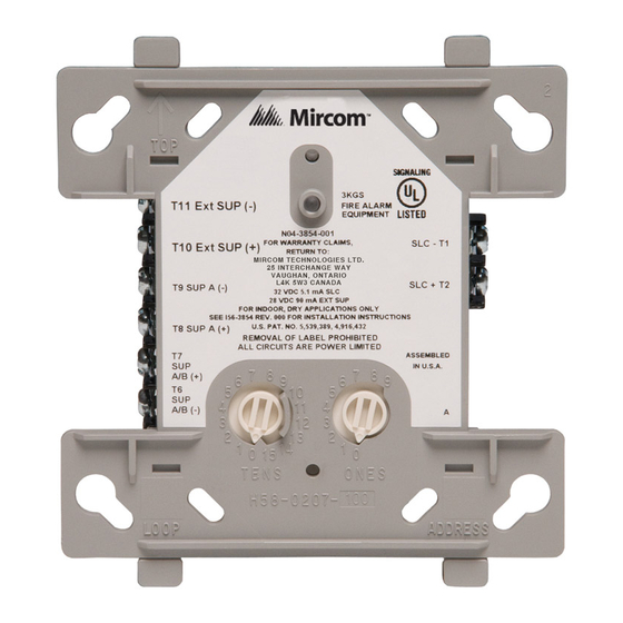
fIgURE 1. CONTROLS AND INDICATORS:
MC-460-008
15 to 32 VDC
5.0mA (LED on)
400 μA, 1 communication every 5 seconds, 47k EOL
47K Ohms
40 Ohms
11 Volts
400µA
32˚F to 120˚F (0˚C to 49˚C)
10% to 93% Non-condensing
4
1
/
˝ H x 4˝ W x 1
1
/
˝ D (Mounts to a 4˝ square by 2
2
4
SMB500 Electrical Box
C0917-01
firealarmresources.com
25 Interchange Way, Vaughan Ontario, L4K 5W3
1
/
˝ deep box.)
8
MOUNTINg
The MIX-M500MAP mounts directly to 4-inch square electrical boxes (see
Figure 2). The box must have a minimum depth of 2
mounted electrical boxes (SMB500) are available from System Sensor.
fIgURE 2. MODULE MOUNTINg:
WIRINg
NOTE: All wiring must conform to applicable local codes, ordinances, and
regulations. This module is intended for power limited wiring only.
1.
Install module wiring in accordance with the job drawings and appropri-
ate wiring diagrams.
2.
Set the address on the module per job drawings.
3.
Secure module to electrical box (supplied by installer), as shown in Fig-
ure 2.
1
Phone: 905.660.4655; Fax: 905.660.4113
/
inches. Surface
1
8
ISOLATED
QUADRANT
C1044-00
I56-3314-000
©2008 Mircom
Advertisement
Table of Contents

Subscribe to Our Youtube Channel
Related Manuals for Mircom MIX-M500MAP

Summary of Contents for Mircom MIX-M500MAP
- Page 1 NOTICE: This manual should be left with the owner/user of this equipment. gENERAL DESCRIPTION The MIX-M500MAP Monitor Module is intended for use in intelligent, two- wire systems, where the individual address of each module is selected using the built-in rotary decade switches. It provides either a 2-wire or 4-wire fault tolerant initiating circuit for normally open contact fire alarm, supervisory, or security devices.
- Page 2 SIGNAL LINE CIRCUIT (SLC) 32 VDC MAX. EOL RESISTOR TWISTED PAIR IS INTERNAL AT IS RECOMMENDED TERMINALS 8 AND 9 ALL WIRING SHOWN IS SUPERVISED AND POWER LIMITED INSTALL CONTACT CLOSURE DEVICES PER MANUFACTURER’S INSTALLATION INSTRUCTIONS. C0919-03 MC-460-008 I56-3314-000 ©2008 Mircom firealarmresources.com...
Need help?
Do you have a question about the MIX-M500MAP and is the answer not in the manual?
Questions and answers