Table of Contents
Advertisement
Quick Links
Advertisement
Table of Contents

Related Manuals for ARJAY ENGINEERING 4100-HCF2


Summary of Contents for ARJAY ENGINEERING 4100-HCF2
- Page 1 MODELS: 4100-HCF2 FLOATING OIL THICKNESS MONITOR USER MANUAL (REV: 3.0) ARJAY ENGINEERING 2851 Brighton Road TEL: ++1 (905) 829-2418 WEBSITE: www.arjayeng.com Oakville (Toronto), Canada FAX: ++1 (905) 829-4701 EMAIL: arjay@arjayeng.com L6H 6C9 NORTH AMERICA: 1-800-387-9487...
- Page 2 THIS PAGE INTENTIONALLY LEFT BLANK...
-
Page 3: Table Of Contents
CONTROLLER SETTING SHEET ................ 31 10.0 MODBUS MAP AND DETAIL (OPTIONAL) ............34 10.1 Modbus Commands Supports .................... 34 10.2 Register Map ........................34 11.0 DETAIL ELECTRICAL AND DIMENSIONAL DRAWINGS ........35 4100-HCF2 Revision 3.0 P a g e 3 | 35... - Page 4 ..........25 FIGURE 17 – FULL CALIBRATION SET-UP SCREEN VIEW ..........26 FIGURE 18 – MANUAL CALIBRATION SET-UP SCREEN VIEW .......... 26 FIGURE 19 – DIAGNOSTIC INFORMATION SCREEN VIEW ..........27 4100-HCF2 Revision 3.0 P a g e 4 | 35...
-
Page 5: Specification
Float Sensor Input: Capacitance Sensor with PMC input External Level Sensor Input: 4-20mA input from Level transmitter Instrument Performance: Accuracy 0.04% of full scale pF Resolution 0.007% (0.07pF at 1000pF) 4100-HCF2 Revision 3.0 P a g e 5 | 35... - Page 6 0 to +55 °C Float Sensor with potted PMC (Optional high temperature sensor available. Consult factory) Relative humidity 0 to 95% (non-condensing) Installation Category Pollution Degree Equipment mobility Fixed Mechanical Specification: Refer to Dimensional Drawing 4100-HCF2 Revision 3.0 P a g e 6 | 35...
-
Page 7: Use Hazard Information
Indicates a potentially or imminently hazardous situation which, if not DANGER avoided, will result in death or serious injury. Indicates a situation which, if not avoided, may cause damage to the NOTICE instrument. Information that requires special emphasis. 4100-HCF2 Revision 3.0 P a g e 7 | 35... -
Page 8: Instrument Overview
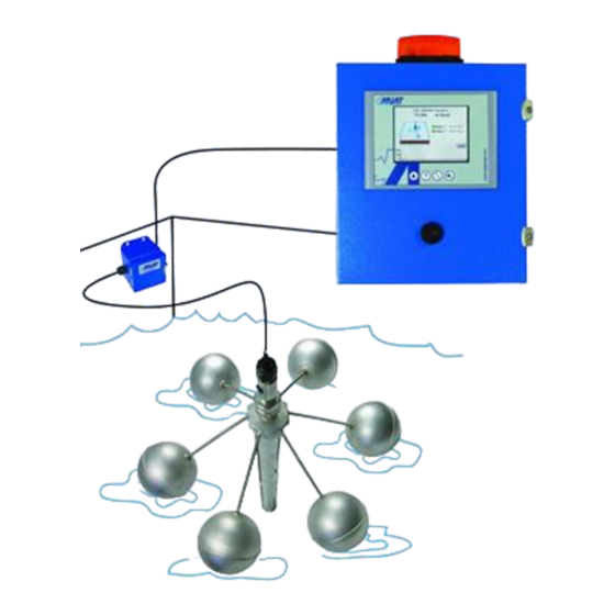
The monitoring system is comprised of one main control panel, floating sensor with potted PMC card. Optional Remote alarm panels can also be added that will display and provide audio/visual alarms Figure 1 – Instrument System Overview 4100-HCF2 Revision 3.0 P a g e 8 | 35... - Page 9 A display of the overall level of the sump or tank is provided as an option. This would require a 4-20mA input from an external level sensor. Relay 4 can be enabled as a level sensor alarm. 4100-HCF2 Revision 3.0...
-
Page 10: Features
Diagnostic, set-up and Help menus on all screens Four alarm relays Optional analog outputs and RS-485 communication Optional level display in % and unit of measurement Model Number Table 4100-HCF2 - h – Custom vs. b - Enclosure a - Power Input Standard 0 –... -
Page 11: Installation
The Internal ground screw provided in this enclosure must be used for equipment grounding connection. CAUTION The External ground screw is provided for use only as a supplemental connection where required (or, permitted) by local codes or authorities. 4100-HCF2 Revision 3.0 P a g e 11 | 35... -
Page 12: Sensor Installation
Any splitter junction box must be mounted above the flood level and sealed from condensation in the conduit. In applications of high turbulence and extremes of level change, additional guide restraints may be required. Consult Arjay Engineering. To ensure proper operation and electrical safety, make sure the NOTICE controller is electrically grounded. -
Page 13: Figure 3 - Typical Oil Thickness Monitor Application Overview
Figure 3 – Typical Oil Thickness Monitor Application Overview 4100-HCF2 Revision 3.0 P a g e 13 | 35... -
Page 14: Electrical Installation Overview
*Shielded wire is required on all installations. Maximum wire length is 1km between controllers to sensor float. Refer to the detailed electrical drawings included at the back of this manual. 4100-HCF2 Revision 3.0 P a g e 14 | 35... -
Page 15: Permanent Power Connection (Ac Powered Models Only)
Direct Current (DC) Power off Courant continu ArróÕ (mise hors tension) Normally closed relay contacts Live Contacts Repos Sous tension Power on Ground Marche (mise sous tension) Terre Neutral Neutre 4100-HCF2 Revision 3.0 P a g e 15 | 35... -
Page 16: Startup
100% maximum oil level will be required to be entered during calibration. Note: The 100% oil depth is a maximum of 25mm for the A00761 style sensor and 300mm for the A00765 style sensor. 4100-HCF2 Revision 3.0 P a g e 16 | 35... -
Page 17: Keypad Main Menu Entry
Buzzer Silence During an alarm condition the audio can be silenced. Silencing at any panel will silence all panels. The audio alarm will automatically re-set when the alarm clears. 4100-HCF2 Revision 3.0 P a g e 17 | 35... -
Page 18: Password
2000. Touch within the Password box, a keyboard will display. After the password is entered, press the Return key to complete. Then press OK in Login screen. Menus can then be accessed. Figure 6 – Password Screen View 4100-HCF2 Revision 3.0 P a g e 18 | 35... -
Page 19: Controller Network
40% change over a period of 10 seconds. If the level returns to a lower point, the mA will follow the new path with the same dampening affect. 4100-HCF2 Revision 3.0 P a g e 19 | 35... -
Page 20: Alarms Setup
Disabled and will remove that relay from the main screen display. It will disable the relay from functioning. If it presently reads Disabled, press the icon to Enable the relay. **If selected as oil alarm only or level sensor for relay 4. 4100-HCF2 Revision 3.0 P a g e 20 | 35... -
Page 21: Figure 10 - Alarm Setup Screen View
When in Failsafe mode and during a normal condition, the N.O. contact is closed and the N.C. contact is open. WIRE ACCORDINGLY. 4100-HCF2 Revision 3.0 P a g e 21 | 35... -
Page 22: Date And Time
The 4100-HCF has a real time clock to show current date and time. Press change button to modify the current date and time if required. Press Enter to update the modified date and time. Figure 11 – Date and Time Screen View 4100-HCF2 Revision 3.0 P a g e 22 | 35... -
Page 23: Analog (Ma) Output (Optional)
Output Trim (Optional) mA Output Trim: Allows user to trim/modify mA output values. This modification requires a special password which can be obtained from Factory (Arjay Engineering Ltd.) if required. Buzzer and Strobe Beacon (Optional) Allows a Buzzer or Strobe Beacon is ordered, they are factory wired to internal relays. They can be set in the same way as the Alarm relays. -
Page 24: Calibration
If a calibration cannot be performed at the time of the reminder, this can be reset to a later date by entering the number of days until the next reminder is desired. Press “Enter” icon to activate the Reminder countdown. 4100-HCF2 Revision 3.0 P a g e 24 | 35... -
Page 25: Quick Calibration
Slope This is factory preset. The factory default is in pF/mm. If the display engineering units have been changed (ie. to inches), the slope must be mathematically corrected and re-entered. 4100-HCF2 Revision 3.0 P a g e 25 | 35... -
Page 26: Full Calibration
This allows a user to override any of the previous calibration values and enter predetermined or observed calibration values. For the Quick calibration the second cal point was determined from slope and depth of oil for 100%. Figure 18 – Manual Calibration Set-up Screen View 4100-HCF2 Revision 3.0 P a g e 26 | 35... -
Page 27: Diagnostic Information
This is set as pF/mm. It is important to convert this value when changing engineering units. e.g. Inches would be converted from 0.182 pF/mm to 4.623 pF/inches (A00765 Float). This slope is based on diesel fuel at 2.1 dielectric constant. 4100-HCF2 Revision 3.0 P a g e 27 | 35... - Page 28 Offset: The offset is the capacitance of the sensor in the vessel under a 0% oil condition. Calibration Points: These are the calibration values recorded after the last successful calibration. Last Calibrated: During a successful calibration, the calibration date will be recorded. 4100-HCF2 Revision 3.0 P a g e 28 | 35...
-
Page 29: Troubleshooting
Under normal operating conditions, both LED’s should be Lit and Flashing continuously. Check wiring between 4100 Signal Converter (A00740) and RS485 (CM1241) Module. Confirm 24VDC power to 4100 Signal Converter (A00740). 4100-HCF2 Revision 3.0 P a g e 29 | 35... - Page 30 Check that the correct AKC values are entered in calibration menu. These values are on the side of floating sensor (A00761) or inside junction box (A00765) OR Section 9.0 of the manual. 4100-HCF2 Revision 3.0 P a g e 30 | 35...
-
Page 31: Controller Setting Sheet
Alarm action above OR below alarm level Above Action Amount of time the level must be in an alarm Relay 1: Alarm Delay 10 sec condition (based on Relay 1 alarm value and (ON) 4100-HCF2 Revision 3.0 P a g e 31 | 35... - Page 32 (based on Relay 4 alarm value and Relay 4: Alarm Delay Action settings) before the relay trips to the 10 sec (OFF) normal condition (condition set by Relay 4 Failsafe setting). 4100-HCF2 Revision 3.0 P a g e 32 | 35...
- Page 33 (based on Relay 2 alarm value and Optional Action settings) before the relay trips to the 10 sec Buzzer / Strobe normal condition (condition set by Relay 2 Setting Failsafe setting). 4100-HCF2 Revision 3.0 P a g e 33 | 35...
-
Page 34: Modbus Map And Detail (Optional)
Calibration point CAL 2 (pF) capacitance 40021 real Depth of Oil 40023 real Percent of Oil 40025 real Level sensor_mA input level depth 40027 real Level sensor_mA input level percent 4100-HCF2 Revision 3.0 P a g e 34 | 35... -
Page 35: Detail Electrical And Dimensional Drawings
Drawings are included in this section that are specific to your model ordered. If drawings are not included here, record the serial number on the left outside wall of the main panel and contact: ARJAY ENGINEERING TECHNICAL SUPPORT (800) 387-9487 +1 (905) 829-2418 www.arjayeng.com...
Need help?
Do you have a question about the 4100-HCF2 and is the answer not in the manual?
Questions and answers