Table of Contents
Advertisement
Quick Links
Advertisement
Table of Contents

Related Manuals for ARJAY ENGINEERING HYDROSENSE 2410


Summary of Contents for ARJAY ENGINEERING HYDROSENSE 2410
- Page 1 MODEL: HYDROSENSE 2410 OIL IN WATER MONITOR USER MANUAL (REV: 5.0) ARJAY ENGINEERING LTD. 2851 Brighton Road Tel: ++1 (905) 829-2418 Web: www.arjayeng.com Oakville (Toronto), Canada Fax: ++1 (905)829-4701 Email: arjay@arjayeng.com L6H 6C9 North America: 1-800-387-9487...
- Page 2 This page intentionally left blank...
-
Page 3: Table Of Contents
TABLE OF CONTENTS Please read the HydroSense Installation Notes (3.1) prior to locating NOTICE and mounting the enclosures. SPECIFICATIONS ............................ 5 1.0 USE HAZARD INFORMATION ....................... 6 2.0 INSTRUMENT OVERVIEW ......................7 FEATURES ..............................7 DESCRIPTION ..............................7 ... - Page 4 9.0 CONTROLLER SETTING SHEET ....................24 10.0 SAMPLE PREPARATION (FOR CALIBRATION OR TESTING) ..........25 11.0 PERIODIC TESTING AND MAINTENANCE ................26 11.1 PERIODIC TESTING ..........................26 11.2 FLOW PLATE CLEANING ........................27 11.3 LAMP REPLACEMENT ..........................
-
Page 5: Specifications
SPECIFICATIONS Specifications are subject to change without notice: Specification Details Power Input: 100 -130VAC* OR 207 - 253VAC* 50/60 Hz, 200 VA max, (Specify at the time of OPTIONAL: 24 VDC @ 3.5 A max order) *Operational Range User Interface: Display Four line LCD with simultaneous display in PPM, Cal Location, current temperature, and bar graph... -
Page 6: Use Hazard Information
(USCG certified) * UL certified at 120 10% VAC and 230 10% VAC ** The HydroSense 2410 has been third party tested and certified that it is in compliance with the IMO MEPC.107 (49) guidelines. The MEPC 107(49) guidelines require that the site must log and retain data for 18 months. A sample stream by-pass alarm must also be installed and logged. -
Page 7: Instrument Overview
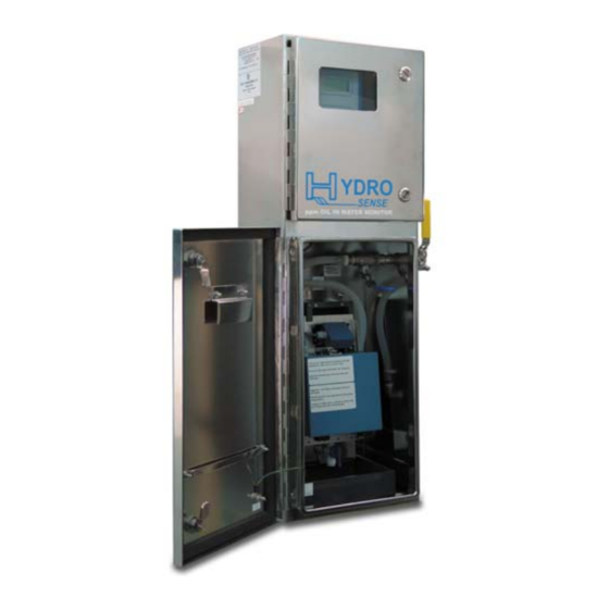
No moving parts, complete maintenance without turning off the sample stream DESCRIPTION The HydroSense Oil in Water Monitor from Arjay Engineering Ltd. has been designed for municipal and industrial applications to measure PPM levels of petroleum hydrocarbons in aqueous solutions. Typical applications include PPM trace amounts of oil in effluent water from storm water runoff, oil in cooling water, produced water, and oil/water separators. -
Page 8: Interferences And Affects To Accuracy
INTERFERENCES AND AFFECTS TO ACCURACY The UV fluorescence technique monitors the intensity of light emitted from the passing stream at a selected wavelength band. This technique can be quite selective by eliminating the light affect of compounds in the water that do not share the same fluorescence characteristics of hydrocarbons. -
Page 9: Routine Cleaning Program
If an interfering background chemical changes in concentration, the HydroSense will sense this change. Consideration to this affect is important for alarms and recording. Filtering of the water, changes to chemical use, or special light filtering may be required to provide more stable readings. The periodic introduction of fluorescing chemicals into the water may also affect the reading. -
Page 10: Installation
INSTALLATION If any damage to the instrument is found, please notify an Arjay NOTICE Engineering representative as soon as possible prior to installation. NOTICE Qualified Personnel must undertake all installations. If the equipment is used in a manner not specified by the manufacturer, WARNING the protection provided by the equipment may be impaired. -
Page 11: Glossary Of Symbols
9) For non-purged/pressurized models the outlet of the tube should be open to air, not submerged in water or a process which would cause a backpressure. This could result in a restriction of the effluent flow and spillage within the lower chamber. For purged/pressurized models, a slight and constant backpressure is required to maintain a cabinet pressure. -
Page 12: Unit Installation
UNIT INSTALLATION Locate an area that is environmentally protected from wide variances in temperature and humidity. Indoor installations are recommended. When selecting the location, consider that regular maintenance and testing is desirable for the proper and accurate operation of the instrument. If the sample input is not from a pumped source, locate the instrument in a position that will receive a continuous representative sample from the process stream. -
Page 13: Figure 2 - Flow Plate Secure Against Tray
Insert the flow plate as shown below. The flow plate has a special reflective core and must be placed in the Tray with the etched "UP" side facing out (toward you). Snug the knurled screws to hold the flow plate in place. KNURLED KNURLED SCREWS... -
Page 14: Permanent Power Connection (Ac Powered Models Only)
For non-purged/pressurized models the outlet of the tube should be open to air, not submerged in water or a process, which would cause a backpressure. This would result in an overflow inside the chamber. For purged/pressurized models, a slight and constant backpressure is required to maintain a cabinet pressure. -
Page 15: Startup And Settings
STARTUP AND SETTINGS Calibration must be performed after installation and any lamp NOTICE replacement. Figure 4 - USER INTERFACE NOTES ON VALUE ENTRY When entering in numeric values, the cursor can be backspaced to correct mistakes by pressing the DISPLAY key. This is only true if the cursor is not at the beginning of the displayed value, in which case the DISPLAY menu is entered. -
Page 16: Password Protection
PASSWORD PROTECTION A password must be entered to access any of the 3 value entry menus (CALIB, CONTROL, SETUP> 5- System) from the normal operating display menu. The factory default password is 2000. A customer password may be added from the setup menu as described in section 8.1.4 Settings. The prompt for entering the password is always 9999 regardless of the actual password. -
Page 17: Control Setup (
CONTROL SETUP (<CONTROL> K To access the control setup settings, you will require a password. The password is “2000”. RELAY SETTINGS <1> Four relay alarm points are available for remote alarm. Of these, two are general-purpose alarm relays with user settable alarm points, dead band (differential alarm points), and time delay. The remaining two relays are to indicate Maintenace alarm (R3) and lamp failure (R4).Key) -
Page 18: Calibration Setup (
The door MUST be closed to eliminate any background light interference during and after calibrations. CALIBRATION For Calibration, the Hydrosense 2410 can accept up to 5 sample points to draw a calibration curve. A calibration curve is used because some samples may not be linear as concentrations increase. 6.2.1 AUTOMATIC CALIBRATION <1-AUTO>...Key) -
Page 19: Manual Calibration With Laboratory Results
Disconnect the inlet of clean water and connect the prepared sample into the inlet. Pump the prepared sample through the Hydrosense 2410. Press <ENTER> to input ppm value of the 2nd point. Enter the known or unknown* ppm value of stream concentration (i.e., 30.0 PPM). -
Page 20: Light Reference And Temperature Setting
Press <DISPLAY> to main display menu. 6.2.5 CHANGE CALIBRATION LOCATION There are 10 calibration locations in Hydrosense 2410 (Cal 0 – Cal 9). Each location can have up to 5 points to draw a calibration curve. The procedure to change calibration location is as follows: Press the <CALIB>... -
Page 21: Setup (Operation And Diagnostics) (
SETUP (OPERATION AND DIAGNOSTICS) (<SETUP> K There are a number of diagnostic screens to monitor the performance of the unit. AMPLIFIED SIGNAL <1> Press the <SETUP> key then Press <1> for AmpSig. This screen displays the FLR (Sample Fluorescence) and the REF (Lamp Reference) signal values AFTER amplification.Key) -
Page 22: Filter <2
7.5.2 FILTER <2> Press <2> for filter. The moving average filter tracks the average of the last # of samples. Higher values provide more stable readings. Max value is 1000. The default value is 960. 7.5.3 UNITS <3> Press <3> for units. There are 3 units are available: ppm, FLR and mg/L. Press <1> for ppm, <2> for FLR and <3>... -
Page 23: Troubleshooting
TROUBLESHOOTING CONDITION DO THIS The controller is not receiving signals from receiver and lamp. Check Wiring. If wiring checks out, call Arjay Technical Support and record the following data. Display Menu show: Press <SETUP>, then press <1> for AMPSIG, and ERROR recording the following data: Check Lamp... -
Page 24: Controller Setting Sheet
CONTROLLER SETTING SHEET FACTORY USER PARAMETER DESCRIPTION SETTING SETTING To compensate for fluorescence light source degradation, the lamp light intensity value is captured during calibration and is subsequently REF at used to compensate the fluorescence signal. Calibration This captured reference value may be viewed in the Calibrate menu. -
Page 25: Sample Preparation (For Calibration Or Testing)
10.0 SAMPLE PREPARATION (F ALIBRATION OR ESTING Testing may be preformed in a number of ways. An unknown concentration may be used to provide a response test. This does not verify the accuracy or calibration of the instrument but does confirm that it will respond and alarm to a high concentration condition. -
Page 26: Periodic Testing And Maintenance
11.0 PERIODIC TESTING AND MAINTENANCE NOTICE Calibration must be performed after installation and any lamp replacemnt. 11.1 PERIODIC TESTING The HydroSense is an electronic device used for environmental and personal protection, as well as general process monitoring. As with any calibrated sensing device, wetted parts may become contaminated and the light source can deteriorate over time. -
Page 27: Flow Plate Cleaning
11.2 FLOW PLATE CLEANING The unit is designed for quick and easy cleaning. Remove the Blue Lamp Box and place on the chamber door to access the flow plate. Wipe the flow plate with a clean damp cloth. The flow plate may be removed for cleaning if desired. - Page 28 This warranty extends to Arjay supplied equipment and includes carbon monoxide sensing cells. All other consumable gas sensor cells are excluded from this additional warranty. Arjay Engineering Ltd. arjayeng.com admin/forms/admin/warranty2018...
Need help?
Do you have a question about the HYDROSENSE 2410 and is the answer not in the manual?
Questions and answers