
Related Manuals for ARJAY ENGINEERING 4500-RMS


Summary of Contents for ARJAY ENGINEERING 4500-RMS
- Page 1 4500-RMS User Manual Arjay Engineering 2851 Brighton Road Oakville, Canada, L6H6C9 Phone: ++1 (905) 829-2418 Fax: ++1 (905) 829-4701 www.arjayeng.com arjay@arjayeng.com...
-
Page 2: Table Of Contents
4500-RMS Remote Monitoring System Instruction & Maintenance Manual Table of Contents SECTION A Contents Page Introduction ................. 3 Description of Unit / Control Functions ........3 Installation .................. 4 Mounting Instructions ..............4 Electrical Wiring ................4 Wiring Diagrams ................. 4 III. -
Page 3: Introduction
Introduction The 4500-RMS microprocessor based controllers are designed to provide a wide range of remote monitoring functions. The controller is programmed through a front panel keypad or via the internet through WebAdvantage and can be configured to provide customized remote monitoring for your application. Your particular unit’s functions can be determined by comparing the units model number to the Model Numbering table listed below. -
Page 4: Installation
Electrical Wiring The 4500-RMS monitor has an internal regulated fused power supply that will operate off of 90 to 250 VAC at 47 to 63 Hz on the incoming wiring. Each output relay is individually protected with a replaceable fuse. Relay outputs will equal incoming line voltage. - Page 5 Relay Card Wiring Motherboard Connections System Card Connections N.O.
- Page 6 4-20mA Input Card Wiring The 4-20mA input card requires that the external device sending the 4-20mA input signal(s) supply the power for the loop. The external power source must not exceed 24 volts DC.
-
Page 7: Front Panel Description
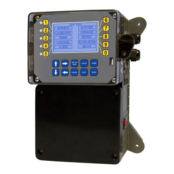
III. Front Panel Description NUMBER Keys- Used to enter new values in the SET UP mode and to access desired sub menus. UP/DOWN - Used to cycle through text options to find desired setting. LEFT/RIGHT - Used to cycle through text or setting options to find desired setting. SET UP/RUN - System initializes into RUN mode. -
Page 8: System Operation Overview
IV. System Operation Overview Operation 4500-RMS controllers have two modes of operation, RUN and SET-UP. - This mode is for normal operation. In the RUN mode the display will show each system’s parameters. If an alarm is present, the ALARM box will flash how many alarms are activated. No settings may be entered or changed in the RUN mode. - Page 9 Set Points The same basic format is used for defining each available analog mA control parameters. >SYSTEM 1 SET POINTS< SET POINTS - For setting the relay set points for the available analog readings. mA OUT mA IN AUX INPUTS NOTE: In the Setpoint pop-up screen the direction (Rising or Falling) of the setpoint can also be set.
- Page 10 4-20mA Input Calibration 4-20mA inputs can be calibrated to ensure that the input seen by the controller from the external device match. It also allows for setting the 4-20mA input into a number range that relates to the value being read. >CURRENT LOOP CALIBRATION<...
- Page 11 Customize This menu allows the user to define the on-screen name of the unit plus the name of each system and relay. The user can also setup the Notepad for each system and 4-20mA Input’s name and unit of measurement. RUN SCREEN - Allows user to select which mA inputs >CUSTOMIZE<...
- Page 12 Alarms ALARMS - Shows any current alarms. >ALARMS< SYS 1 ALARMS Date and Time Set Up DATE AND TIME - For setting the date, time, day and >SET DATE AND TIMES< week on the controller. SET DATE SET TIME SET DAY SET WEEK Friday May 14, 2005 03:04:56 Configure...
- Page 13 History This menu is used to set the history “time stamp” interval, the water meter daily history starting hour, the alarm delay period and the USB history save format. INTERVAL - The amount of time between each history >CONFIGURE HISTORY< time stamp for probe readings.
- Page 14 History The onboard history allows for viewing the history of the mA readings, relay activations, key-pad activity, calibrations, flow meter hourly and daily logs and alarms for each system present. It is also where Notepad data is entered and reviewed. An initial overview page is displayed showing your current sample interval, the calculated number of days the unit can keep probe history for before losing the oldest.
-
Page 15: Webadvantage Setup
VI. WebAdvantage Setup WebAdvantage Connection - SETUP CHECKLIST • Do you have a WebAdv3 USER ID and password? _____ Yes, if ‘No’ proceed to page 18. • Has your account admin added the device and linked it to your USER ID? _____ Yes, if ‘No’ proceed to page 19. - Page 16 USER ID Setup Setting Up a USER ID Before you can view a device, a USER ID must be setup. Note: If you already have a USER ID and are just adding a new device, skip to step 4. Step 1: Visit https://webadvantage.online or access the registration form with the QR...
- Page 17 Admins Only: Add Device and Assign USER ID Setting Up / Accessing a Device Note: USER ID and Company Access Permissions Note: Please allow up to 24 hrs for processing before are required before you can access a device. For controller shows in device list.
-
Page 18: Usb Functions
XS Controller - USB Functions Step 1: The XS is capable of transferring information using a FAT formatted USB drive. The XS has To transfer the contents to the XS history logs three main USB functions as detailed in the fol- ot the USB drive, select -->... - Page 19 XS Controller - USB Functions Step 4: Uploading data to WebAdvantage This is the Configure Screen. From here push If the controller does not have a communications card HISTORY (Button 4) to go to the next screen. you can purchase WEBADV-XSCLOUD storage of your unit’s history.
- Page 20 XS Controller - USB Functions Select --> Config --> USB (Config to USB) by After second update is complete, power down and remove USB. Power back on (after 20 sec- using the Arrow buttons. Then press ENTER. onds) and go to the Configure menu. From here push SYS INFO (Button 9) and con- The User settings will be saved to the USB drive firm that the unit now has the new version and...
-
Page 21: Troubleshooting
VIII. Troubleshooting The 4500-RMS monitor is designed for many years of trouble-free operation. Should a problem occur, refer to the following chart to help identify the problem. If replacement is required, follow the procedures listed in the Warranty and Factory Service portion of this manual.
Need help?
Do you have a question about the 4500-RMS and is the answer not in the manual?
Questions and answers