Table of Contents
Advertisement
Quick Links
distributed by
Original
Assembly and
Maintenance Manual
Linear Unit
Types
Beta 60-SGV-SSS
Beta 70-C-SRS-SSS
Beta 80-SRS-SSS
Beta 80-SGV
Beta 100-D-SSS
Beta 110-SRS-SSS
Beta 110-C-SGV
Beta 120-C-SSS
Beta 140-SRS-SSS
Beta 140-C-SSS
Beta 165-SSS
Beta 165-SGV
Beta 165-C-SGV
Beta 180-SSS
Beta 180-C-SSS
HSB Automation GmbH
In Laisen 74
72766 Reutlingen
Germany
Tel. +49 7121 14498-0
Fax +49 7121 14498-10
info@hsb-automation.de
www.hsb-automation.de
Distributor:
SCHUNK GmbH & Co. KG
Spann- und Greiftechnik
Bahnhofstr. 106 - 134
74348 Lauffen/Neckar
Germany
Tel. +49 7133-103-0
Fax +49 7133-103-2399
info@de.schunk.com
www.schunk.com
FM 240 Master MuW Manual Beta Type S Rev.01
Advertisement
Table of Contents

Related Manuals for HSB Beta 60-SGV


Summary of Contents for HSB Beta 60-SGV
- Page 1 Original Assembly and Maintenance Manual Linear Unit Types Beta 60-SGV-SSS Beta 70-C-SRS-SSS Beta 80-SRS-SSS Beta 80-SGV Beta 100-D-SSS Beta 110-SRS-SSS Beta 110-C-SGV Beta 120-C-SSS Beta 140-SRS-SSS Beta 140-C-SSS Beta 165-SSS Beta 165-SGV Beta 165-C-SGV Beta 180-SSS Beta 180-C-SSS...
-
Page 3: Table Of Contents
distributed by Safety Contents Safety ........................3 Symbols used ......................3 Regulation use ......................3 General safety ......................4 Use in explosive environments .................. 4 Technical condition of the linear unit ................5 Modifications to the linear unit ................... 5 Requirements for personnel.................. - Page 4 Safety About this manual Applicability This manual applies to the following linear units with spindle drive: • Beta 60-SGV-SSS • Beta 70-C-SRS-SSS • Beta 80-SRS-SSS • Beta 80-SGV • Beta 100-D-SSS • Beta 110-SRS-SSS • Beta 110-C-SGV •...
-
Page 5: Safety
distributed by Safety Safety The Assembly and Maintenance Manual is a component element of the product package, and must always be kept to hand as a reference source. The Manual must be passed on if the unit is sold on or given away. If there is anything in this manual which you do not fully understand, please be sure to contact the manufacturers. -
Page 6: General Safety
distributed by Safety General safety Preconditions for The linear unit must not be put into operation until the machine or line operation installed into which it is conforms to the following: • Relevant accident prevention regulations • Generally accepted safety standards •... -
Page 7: Technical Condition Of The Linear Unit
distributed by Safety Technical condition of the linear unit State of the art The unit conforms to the current state of the art and applicable rules and regulations. The unit conforms to the EU Machinery Directive, harmonised European standards or corresponding national standards: •... -
Page 8: Obligations Of The Operating Company
distributed by Safety • Installing safety limit switches • Mounting a drive unit • Checking the direction of rotation of the drive Obligations of the operating company Instruction of In accordance with EU Health and Safety Directive 89/655/EEC articles personnel 6(1) and 7 and with the Framework Directive 89/391/EEC articles 1(1) and 6(1), the company operating the linear unit must provide personnel assigned to install, operate, maintain, repair or dismantle the unit with... -
Page 9: Warranty
distributed by Warranty Warranty The warranty conditions are laid down in the terms and conditions of delivery and payment issued at time of order. Warranty cover will be voided if: • the unit is not operated in accordance with the stipulated regulation use;... -
Page 10: Technical Data - Standard Model
distributed by Technical data – Standard model Technical data – Standard model Technical data - Linear unit Sizes Beta type with spindle drive Beta 60 Beta 70-C Drive element Max. speed [rpm] 3000 1500 3000 1500 3000 1500 3000 1500 Spindle diameter [mm] Spindle pitch [mm] Moment of inertia [kgm²/m]... - Page 11 distributed by Technical data – Standard model Technical data - Linear unit Sizes Beta type with spindle drive Beta 80 Beta 100-D Drive element Max. speed [rpm] 3000 1500 3000 1500 3000 1500 3000 1500 Spindle diameter [mm] Spindle pitch [mm] Moment of inertia [kgm²/m] 8.50 x 10 2.25 x 10...
- Page 12 distributed by Technical data – Standard model Technical data - Linear unit Sizes Beta type with spindle drive Beta 110 Beta 110-C Beta 120-C Drive element Max. speed [rpm] 3000 1500 3000 1500 3000 1500 3000 1500 Spindle diameter [mm] Spindle pitch [mm] Moment of inertia [kgm²/m] 2,25 x 10...
- Page 13 distributed by Technical data – Standard model Technical data - Linear unit Sizes Beta type with spindle drive Beta 140 Beta 165 Drive element Max. speed [rpm] 3000 1500 3000 1500 3000 1500 3000 1500 Spindle diameter [mm] Spindle pitch [mm] Moment of inertia [kgm²/m] 2.25 x 10 1.65 x 10...
- Page 14 distributed by Technical data – Standard model Technical data - Linear unit Sizes Beta type with spindle drive Beta 140-C Beta 180-C Beta 180 Drive element Max. speed [rpm] 3000 1500 3000 1500 3000 1500 Spindle diameter [mm] Spindle pitch [mm] Moment of inertia [kgm²/m] 2,25 x 10 6,45 x 10...
- Page 15 Technical data – Standard model Forces and moments - Beta linear unit with spindle drive Type designation Dynamic forces [Nm] Dynamic moments [Nm] no-load Beta 60-SSS 4000 1800 1200 Beta 60-SGV 4000 Beta 70-C-SRS 2000 1000 Beta 70-C-SSS 2000 1800 1200 Beta 80-SRS...
- Page 16 distributed by Technical data – Standard model Dynamic load ratings of ball screw drives - Beta linear unit Nominal Ø in Model and size Pitch in [mm] [mm] 9300 Beta 70 14300 Beta 70-C 7450 10500 Beta 60 13500 Beta 80 11500 Beta 100-D 12300...
- Page 17 distributed by Technical data – Standard model Dynamic load ratings of rail guides - Beta linear unit Model Size Number Number Load rating Preten-sion [Nm] Guide Guide of rails per carriage spacing in spacing in carriages direction x direction y THK / Rex* THK / Rex* THK / Rex*...
- Page 18 distributed by Technical data – Standard model Tightening torques [Nm] for fixing screws Fixing screws The figures given are intended as guides. DIN912/ISO4762-8.8 22,0 43,0 74,0 For shorter insertion depths, the figures must be adjusted DIN912/ISO4762-10.9 22,0 43,0 74,0 accordingly. DIN912/ISO4762-12.9 22,0 43,0...
-
Page 19: Product Description
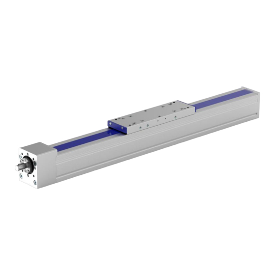
distributed by Product description Product description Linear unit with spindle drive Fixed bearing Movable bearing Carriage Base profile Lubricating nipple Driver Cover band Figure 1: Component assemblies of the Beta 60 linear unit with spindle drive FM 240 MuW Beta Type S Rev.01 2022-09-08... - Page 20 distributed by Product description Roller bearing and linear guidance system Carriage Roller bearing guidance system Base profile Recirculating ball bearing Thread drive Guide rails Figure 2: Guide elements A mechanical linear unit converts rotational motion into linear motion and is used to move loads quickly, safely and precisely from one position to another.
- Page 21 distributed by Product description The effective range can be flexibly configured. Multiple linear units of the Alpha, Beta or Delta type can be arranged two-dimensionally (2 axes) or three-dimensionally (3 axes). Driven linear units can be connected to non-driven units of the same type by a plate, to be able to take large-area loads for example.
-
Page 22: Transportation And Storage
distributed by Transportation and storage Transportation and storage The mechanical linear unit is a precision item. Its mechanism may be damaged by heavy jolting, resulting in impairment of its functions. Risk of damage by heavy jolting or bending! Transport the assembled linear unit only with the transit protection fitted. -
Page 23: Installation And Adjustment
distributed by Installation and adjustment Installation and adjustment The linear unit can be attached by the following methods: • On mounting rails • By screws inserted into the sliding blocks • By screws inserted into the factory-fitted tapped hole rails ... -
Page 24: Screwing The Linear Unit Into Place From Below
distributed by Installation and adjustment Screwing the linear unit into place from below Figure 4: Sliding blocks (1) in the groove on the underside of the base profile Attach the linear unit by the fixing screws from below using the sliding blocks or the tapped hole rails in the aluminium base profile (figure 3). - Page 25 distributed by Installation and adjustment Inductive limit switch Switching cam Band marking safety zone Figure 5: Inductive limit switches The limit switches must switch so that the carriage comes to a stop immediately before the safety zone. The safety zone is factory-marked on the unit by a band (3).
-
Page 26: Setting The Positions Of The Mechanical Limit Switches
distributed by Installation and adjustment 6.3.2 Setting the positions of the mechanical limit switches Mechanical safety limit switches (NC contacts) must be used if a hazard is posed to personnel as soon as the electric drive fails to shut down. The drive may only be started up when all limit switches are connected and correctly set! A combination with inductive proximity switches is possible. -
Page 27: Mounting A Drive Unit
distributed by Installation and adjustment Procedure Connect the power to the limit switches. Slacken the bracket fixing screw (figure 5). Run the carriage as far as the safety zone. Move the limit switch until it trips. Tighten the bracket fixing screw. Check the correct position of the limit switch: Move the carriage manually and observe the switching operation. -
Page 28: Mounting A Motor
distributed by Installation and adjustment 6.4.1 Mounting a motor Clutch half 1 Motor housing Clutch ring Diameter on motor housing Clutch half 2 Figure 8 Motor housing with motor clutch on drive pin Procedure Place the motor and the clutch components in mounting position adjacent to the linear unit. -
Page 29: Start-Up
distributed by Start-up Tightening torque [Nm] of clamping screws Screw Torque Start-up Risk of personal injury or damage to other system components caused by rapid linear motion of the transport carrier, caused by thrown loads. Only authorised specialist personnel may start up the linear unit. Risk of crushing due to incorrect direction of movement of the transport devices. -
Page 30: Operation
distributed by Operation Trial run To prevent accidents, collisions and possible errors in the programming, move the linear unit along the stroke several times at such a low speed that it can be stopped in good time in case of an emergency. -
Page 31: Shutdown
distributed by Shutdown Shutdown Risk of personal injury or damage to other system components caused by falling system components. Only authorised specialist personnel may disassemble the linear unit. Cut the power to the machine/line. Dismantle the drive from the linear unit. Detach the linear unit from the machine/line. - Page 32 distributed by Maintenance Initial lubrication Carry out an initial lubrication after starting up the unit for the first time. A basic lubrication was applied at the factory. Refer to the lubrication regulations on the following pages. Note Under normal operating conditions (dry environment, no dusts, etc.), the roller guide is lubricated for life with integrated lubricating felts.
- Page 33 distributed by Maintenance Schedule for lubrication point S (for ball screw drive) BSD* type Lubrication intervals at Grease quantity Grease type roll-overs [cm³] per ball screw nut 1204 0,50 Greases to DIN 51825- KP2N-20, e.g. Klüberplex 1205 0,55 BE 31-102 1605 1,70 ...
- Page 34 distributed by Maintenance Schedule for lubrication point F (for linear guide) Carriage size Lubrication interval Grease quantity Grease type [cm³] per carriage 15 with ball chain approx. 0.4 Greases to DIN 51825- KPE1R-20, e.g. Klüberplex 20 with ball chain approx. 0.6 BE 31-102 25(L) with ball chain approx.
-
Page 35: Replacing Cover Bands
distributed by Maintenance Replacing cover bands To preserve the optimum running of the linear unit and prevent it from being damaged during operation, take care that no foreign bodies penetrate the base profile or other linear unit components during installation and assembly. ... - Page 36 distributed by Maintenance Procedure Loosen the lubricating nipples: − On Beta 60 to 80 Unscrew all screw-fit lubricating nipples (a) about 2 turns so as not to damage the sealing faces. − On Beta 60 to 80 Remove all conical lubricating nipples or the external lubrication ports and unscrew the lubricating adapters (a) about 2 turns so as not to damage the...
- Page 37 distributed by Maintenance end. Make sure the O-rings are fitted on the lubricating apertures on the underside of the carriage and refit the carriage in the correct position. To check that the carriage is correctly installed, run it slowly from one end of the linear unit to the other, ensuring the cover band is held all the time in its guideway.
Need help?
Do you have a question about the Beta 60-SGV and is the answer not in the manual?
Questions and answers