Table of Contents
Advertisement
K2950SCHEDESS_01 – K2950SCHEDESS_02 (E141203X)
25/08/2015
HOW TO REPLACE
A "ECC" CONTROL BOARD WITH
A "IM7" CONTROL BOARD
TUMBLE DRYER "E" SERIES
MOD. 10/14/18/23/34 Kg
FROM MARCH 2002 SERIAL NUMBER E200912064
IMESA S.p.A.
Via degli Olmi 22
31040 Cessalto (TV), Italia
tel. +39.0421.468011
fax +39.0421.468000
www.imesa.it
1
Advertisement
Table of Contents

Related Manuals for Imesa ECC


Summary of Contents for Imesa ECC
- Page 1 K2950SCHEDESS_01 – K2950SCHEDESS_02 (E141203X) 25/08/2015 HOW TO REPLACE A “ECC” CONTROL BOARD WITH A “IM7” CONTROL BOARD TUMBLE DRYER “E” SERIES MOD. 10/14/18/23/34 Kg FROM MARCH 2002 SERIAL NUMBER E200912064 IMESA S.p.A. Via degli Olmi 22 31040 Cessalto (TV), Italia tel.
-
Page 2: Table Of Contents
E200912064 (December damages to people, things and animals. 2009), which were originally equipped with an ECC – ENTITY control board. The installation and maintenance of the here described component must be performed by authorized personnel who knows the product... -
Page 3: Manufacturer Liability
K2950SCHEDESS_01 – K2950SCHEDESS_02 (E141203X) 25/08/2015 and in compliance with European standards 3. MANUFACTURER LIABILITY on the installation and repair of industrial The instructions written in this manual are not machines. replacing, but completing the duties deriving The here describe tumble dryer must be used from the safety and accident prevention laws. -
Page 4: Composition Of The Kit
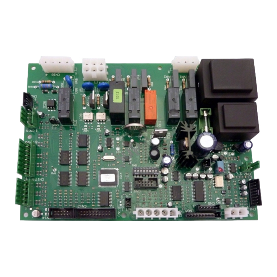
Q.TY present), remove the back panels; 6111105B ES 10/34 IM7 box wiring 4141102X ECC>IM7 Keypad Coin b) The ECC board is placed inside the 2141141 ECC>IM7 Keypad support programmer box, together with the display 2950DISESIM7 IM7 Display board and the keypad. - Page 5 K2950SCHEDESS_01 – K2950SCHEDESS_02 (E141203X) 25/08/2015 ATTENZIONE Before to remove the ECC box, label the JP11 both ways male connectors (the ones with the cables) connectors. To distinguish between one as shown below: and the other connector, check where the door sensor back cable is addressed. The door sensor is contained only in the JP11 connector.
- Page 6 K2950SCHEDESS_01 – K2950SCHEDESS_02 (E141203X) 25/08/2015 d) Remove the wiring plastic ring support (new supports are supplied with the kit). Remove the plastic cable ties, if present, and remove the wiring. Place the wiring, correctly divided, on the above shelf. e) Using the suitable opening on the IM 7 box, bring the display double flat to the CN14 and CN12 connector and install it.
-
Page 7: Installation Of The Kit
K2950SCHEDESS_01 – K2950SCHEDESS_02 (E141203X) 25/08/2015 7. INSTALLATION – K2950SCHEDESS_01 ECC/IM7 CABLING (6141102X) The wiring supplied with the kit is completed with some interconnections to adapt the old machine connection to the new IM 7 control. The wiring code 6141102X was supplied... - Page 8 K2950SCHEDESS_01 – K2950SCHEDESS_02 (E141203X) 25/08/2015 b) Connect the “CO” male connectors to the correspondent “CO” female connectors of the IM 7 board box. The 2 poles connector near CO12 will not be used; it must be closed with the supplied white empty connector.
-
Page 9: Installation Of The Kit K2950Schedess_01 - Contactors Connection
K2950SCHEDESS_01 – K2950SCHEDESS_02 (E141203X) 25/08/2015 d) See the contactor connection instructions given at the paragraph 8. e) Remove the original probe saving the cable: only the last 15 cm of the cable must be cut. Save the probe bulb and the elastic washers needed to fix the new probe to the dedicated bracket. -
Page 10: Keypad And Display
K2950SCHEDESS_01 – K2950SCHEDESS_02 (E141203X) 25/08/2015 d) The cables coming from the connector CO9 must be wired as per the bellow table: LABEL FUNCTIONS Ventilation Cable No. Coming from Going to CO9 – Pos 3 95NC - RMVE RMVE Fan thermal protections CO9 –... - Page 11 K2950SCHEDESS_01 – K2950SCHEDESS_02 (E141203X) 25/08/2015 c) Place the keypad in the middle of the cover opening. Using a marking pen, mark the 4 holes position on the cover inner side. b) Insert the 4 white spacers, 15 mm high (code: 2950DISTA015) on the 4 pinion on the support back.
-
Page 12: K2950Schedess_02
K2950SCHEDESS_01 – K2950SCHEDESS_02 (E141203X) 25/08/2015 e) Connect the double sheathed flat to the connectors on beck of the display board. 10. INSTALLATION – K2950SCHEDESS_02 COIN OPERATED DRYERS Install the CO6 connector only on coin operated dryers. On the contrary, do not install this connector, as the cable 3 and 0F conducts 230V tension. - Page 13 K2950SCHEDESS_01 – K2950SCHEDESS_02 (E141203X) 25/08/2015...
-
Page 14: Electric Diagrams - Conversion Cabling Ecc/Im7 6141102X
K2950SCHEDESS_01 – K2950SCHEDESS_02 (E141203X) 25/08/2015 11. ELECTRIC DIAGRAMS - CONVERSION CABLING ECC/IM7 6141102X... -
Page 15: Electric Diagram Of Im7 Controlled Dryers
K2950SCHEDESS_01 – K2950SCHEDESS_02 (E141203X) 25/08/2015 12. ELECTRIC DIAGRAM OF IM7 CONTROLLED DRYERS... - Page 16 K2950SCHEDESS_01 – K2950SCHEDESS_02 (E141203X) 25/08/2015...
Need help?
Do you have a question about the ECC and is the answer not in the manual?
Questions and answers