Table of Contents
Advertisement
Quick Links
Sensor IQ Easy 2.0 EX
GB
SensorIQEasy2.0EX_UM_GB_V2_0
User Manual
SIMCO (Nederland) B.V.
Aalsvoort 74
7241 MB Lochem - The Netherlands
Telephone +31-(0)573-288333
E-mail
Internet
Traderegister Apeldoorn No. 08046136
IECEx CSA 21.0021 X
CSA Ne 21ATEX2153X
CSAE 21UKEX2694X
Barrier Box
[Ex ib Gb] IIB
2813
Sensor Bar
Ex ib IIB T4 Gb
2813
1
cs@simco-ion.nl
http://www.simco-ion.nl
0518
II (2) G
0518
II 2 G
IEC 60079-0:2017
IEC 60079-11:2011
EN IEC 60079-0:2018
EN 60079-11:2012
GB
1
Advertisement
Table of Contents

Related Manuals for ITW SIMCO ION IQ Easy 2.0 EX


Summary of Contents for ITW SIMCO ION IQ Easy 2.0 EX
- Page 1 SIMCO (Nederland) B.V. Aalsvoort 74 7241 MB Lochem - The Netherlands Telephone +31-(0)573-288333 E-mail cs@simco-ion.nl Internet http://www.simco-ion.nl Traderegister Apeldoorn No. 08046136 Sensor IQ Easy 2.0 EX IECEx CSA 21.0021 X CSA Ne 21ATEX2153X CSAE 21UKEX2694X Barrier Box [Ex ib Gb] IIB 2813 0518 II (2) G...
-
Page 2: Table Of Contents
TABLE OF CONTENTS Preface ............................... 4 Explanation of symbols ........................4 1 Introduction ............................. 5 2 Description and operation ........................ 6 3 Safety .............................. 8 4 Technical specifications ........................9 5 Installation ............................ 11 5.1 Checks ..............................11 5.2 Installing segment units in the Sensor IQ Easy 2.0 EX bar ............... 11 5.3 Shortening the cable(s) between the Barrier Box and a Sensor IQ Easy 2.0 EX bar ........ - Page 3 8 Maintenance ..........................22 8.1 Cleaning the Sensor IQ Easy 2.0 EX ......................22 9 Faults ............................23 10 Repairs and calibration ........................ 24 11 Disposal ............................24 Spare parts ............................24 SensorIQEasy2.0EX_UM_GB_V2_0...
-
Page 4: Preface
Preface This manual is intended for installation and use of the Sensor IQ Easy 2.0 EX. This manual must be available at all times to staff operating the equipment. Read through the entire manual before installing and commissioning the product. Follow the instructions set out in this manual to ensure proper operation of the product and to retain your entitlement under the guarantee. -
Page 5: Introduction
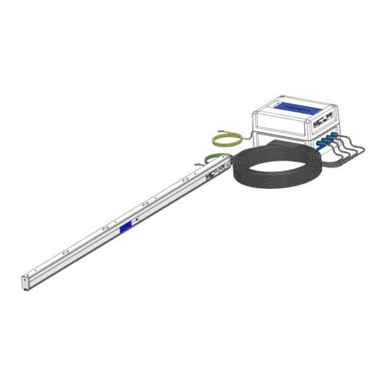
1 Introduction The Sensor IQ Easy 2.0 EX is designed for monitoring electrostatic charge. It consists of 2 parts, the Sensor IQ Easy 2.0 EX bar and a Barrier Box. The Sensor IQ Easy 2.0 EX bar itself is constructed to be used in specific explosion hazardous areas, see chapter 3, Safety. Note: The Barrier Box should be placed outside the hazardous area! Up to 8 sensor segments can be placed in a Sensor IQ Easy 2.0 EX. -
Page 6: Description And Operation
2 Description and operation The Sensor IQ Easy 2.0 EX consists of a bar-shaped aluminium profile. On one or two sides of this profile there are outlets for cables. These cables run to a Barrier Box. The configuration of max. 4 bay’s and max. 4 segments connected to 1 Barrier Box could be placed a second time mirrored in the profile to get up to max. - Page 7 Configuring the Sensor IQ Easy 2.0 EX is done through the Manager IQ Easy. All data from each sensor is communicated to the Manager IQ Easy and is stored for process control. Menu Sensor IQ Easy 2.0 EX Figure 3: Manager IQ Easy The background colour of the sensor icon displays the status of the Sensor.
-
Page 8: Safety
3 Safety The following safety guidelines must be observed in order to prevent physical injury and damage to objects or to the Sensor IQ Easy 2.0 EX itself. Warning: The Sensor IQ Easy 2.0 EX is designed solely for measuring electrostatic charge. The electrical installation and repair must be carried out by an electrical engineer with the relevant training and qualifications and in accordance with the applicable national and local regulations. -
Page 9: Technical Specifications
4 Technical specifications Required power supply 21 – 27 VDC Supply voltage Barrier Box (Un) 250V Max. Cable length from a 50 meter with min. conductor size 0,34 mm Manager IQ Easy to a Barrier Box Connection Standard industrial M12 5-pin connectors Cable length from a Barrier Box to Maximum length is 15 meter (This cable(s) could not be self- a Sensor IQ Easy 2.0 EX... - Page 10 Local signalling LED on Barrier Box Green, Continuously = In operation Green, Flashing = Standby Red = Alarm Orange = Warning See chapter 7 for all indications Functions The Sensor can be monitored using the Manager IQ Easy (see (with IQ Easy platform) also user manual Manager IQ Easy).
-
Page 11: Installation
5 Installation Warning: The electrical installation and repair must be carried out by an electrical engineer with the relevant training and qualifications and in accordance with the applicable national and local regulations. The equipment must be properly earthed. Earthing is necessary to ensure proper and safe operation in hazardous areas. -
Page 12: Shortening The Cable(S) Between The Barrier Box And A Sensor Iq Easy 2.0 Ex Bar
Place the segment in the desired bay of the Sensor IQ Easy 2.0 EX bar. The segment unit can be fitted both ways in a bay. Then tighten the two bolts on the side of the segment unit. Use a small screwdriver, not an electric screwdriver or cordless drill! Figure 5: Placing the Segment unit in the docking station 5.3 Shortening the cable(s) between the Barrier Box and a Sensor IQ Easy 2.0 EX bar The maximum length of the cable(s) between the Barrier Box and the Sensor IQ Easy 2.0 EX is... -
Page 13: Placing The Sensor Iq Easy 2.0 Ex
5.4 Placing the Sensor IQ Easy 2.0 EX Note: Conductive machine parts close to an Sensor IQ Easy 2.0 EX may have a negative influence on its effectiveness. For the best results the Sensor IQ Easy 2.0 EX should be mounted according to figure 6. Mount the Sensor IQ Easy 2.0 EX: •... -
Page 14: Mounting Bracket
5.5 Mounting bracket The Sensor IQ Easy 2.0 EX bar is supplied with at least two mounting brackets. Which could be used to mount Sensor IQ Easy 2.0 EX in various ways. The Barrier Box is supplied with 4 mounting brackets. Note: Keep in mind that the plastic mounting brackets are not electrically conductive. -
Page 15: Mounting Sensor Iq Easy 2.0 Ex (Slide Bracket)
5.6 Mounting Sensor IQ Easy 2.0 EX (slide bracket) Attach the mounting feet (1) on the machine. The triangles (2) have to point in the same direction. For mounting use appropriate M5 mounting material (3). Slide the brackets (4) onto the Sensor IQ Easy 2.0 EX (5). Keep spacing of the brackets (4) and mounting foot (1) equal and lock the bracket (2) with the set screw (6). -
Page 16: Dismantling Sensor Iq Easy 2.0 Ex (Slide Bracket)
5.7 Dismantling Sensor IQ Easy 2.0 EX (slide bracket) - Unscrew the adjusting screws (nr. 7) from the brackets (see figure 8). - Slide the Sensor IQ Easy 2.0 EX with brackets off the mounting feet, in the direction of the triangles to the stop, then pull the Sensor IQ Easy 2.0 EX from the mounting feet straight up. -
Page 17: Commissioning
6 Commissioning Note: - The Sensor IQ Easy 2.0 EX will not function if the sensors are covered. 6.1 Commissioning the Sensor IQ Easy 2.0 EX using the IQ Easy Platform - When the M12 connection cable connects the Barrier Box and the Manager IQ Easy, communication will be established automatically, which is indicated by a flashing status LED and a green background colour behind the emerging sensor symbol. -
Page 18: Selecting Mounting Distance Sensor Iq Easy 2.0 Ex (Expert Mode)
6.3 Selecting mounting distance Sensor IQ Easy 2.0 EX (expert mode) For an accurate measurement the mounting distance whereupon the Sensor IQ Easy 2.0 EX is mounted needs to be entered. By default, this is set to 50mm. If the value of this parameter departs from the actual mounting distance the measure value displayed will not correspond with the actual value. -
Page 19: Set The Warning Minimum Level (Expert Mode)
6.4.1 Set the warning minimum level (expert mode) The Sensor IQ Easy 2.0 EX bar will generate a warning if a segments measured value reaches the Warning set point (during warning/error delay see 6.6 ).It can be easily adjusted: “Warning minimum level” (n)x slide slider or use to go to the desired value and confirm with... -
Page 20: Setting Bar Information Parameters (Expert Mode)
6.8 Setting bar information parameters (expert mode) If desired, various information parameters can be entered as required to make the different devices more recognisable. If desired, adjust the parameters: Device name, Machine position, These are information parameters neither the bar nor the manager will use for calculations. - Select the information page with the parameters to be changed by: “parameter “, enter name or value”, confirm with... -
Page 21: Functional Check
7 Functional check 7.1 Functional check The indication LED on the Barrier Box and the display of the Manager IQ Easy display information on the status of the Sensor. Table 1, overview status indication Display Manager IQ Easy and LED on the Barrier Box Display indication LED Barrier Box Status... -
Page 22: Graphics Tab
7.2.2 Graphics tab The Graphics tab graphically shows the operation in form of bar charts. Each segment is displayed as a vertical bar, and the last will display the average (avg) of all active segments. - red: actual value of the measurement value - yellow: maximum peak value during the last logfile refresh time. -
Page 23: Faults
9 Faults Warning: - Disconnect the power supply before carrying out any work on the unit. - The electrical installation must be carried out by an electrical engineer with the relevant training and qualifications. Table 2, faults Signalling Problem Cause Solution LED on the Barrier No connection... -
Page 24: Repairs And Calibration
10 Repairs and calibration Warning: - Disconnect the power supply before carrying out any work on the unit. - The electrical installation and repair must be carried out by an electrical engineer with the relevant training and qualifications and in accordance with the applicable national and local regulations.
Need help?
Do you have a question about the SIMCO ION IQ Easy 2.0 EX and is the answer not in the manual?
Questions and answers