ITW SIMCO ION IQ Power HL Sensor Installation And Operating Instructions Manual
Hide thumbs
Also See for SIMCO ION IQ Power HL Sensor:

Subscribe to Our Youtube Channel
Related Manuals for ITW SIMCO ION IQ Power HL Sensor


Summary of Contents for ITW SIMCO ION IQ Power HL Sensor
- Page 1 IQ Power ™ HL Sensor INSTALLATION AND OPERATING INSTRUCTIONS I Q Power HL S enso r 52 01 25 2 Rev . A...
-
Page 2: Table Of Contents
TABLE OF CONTENTS 1. SAFETY WARNINGS ................1 2. DESCRIPTION ................... 3 3. SPECIFICATIONS ................4 4. INSTALLATION .................. 5 Unpacking ..........................5 Mechanical Installation ......................5 Intrinsic Safety Barriers ......................7 Sensor Interface ........................7 Electrical Connections ......................8 Purge Gas ..........................10 Sensor Number ........................10 Set Up ..........................11 5. -
Page 3: Safety Warnings
1. SAFETY WARNINGS Simco-Ion recommends that these instructions be read completely before installation or operation is attempted. Failure to do so could result in personal injury and/or damage to the equipment. NOTE – Statements identified with NOTE indicate precautions necessary to avoid potential equipment failure. - Page 4 WARNING – Substitution of components may impair intrinsic safety. (Refer to Control Drawing, Figure 3) AVERTISSEMENT – La substitution de composants peut compromettre la securite intrinseque. (Referez-vous au schema 3) WARNING – Fire Hazard To prevent ignition of flammable or combustible atmospheres, disconnect power before servicing.
-
Page 5: Description
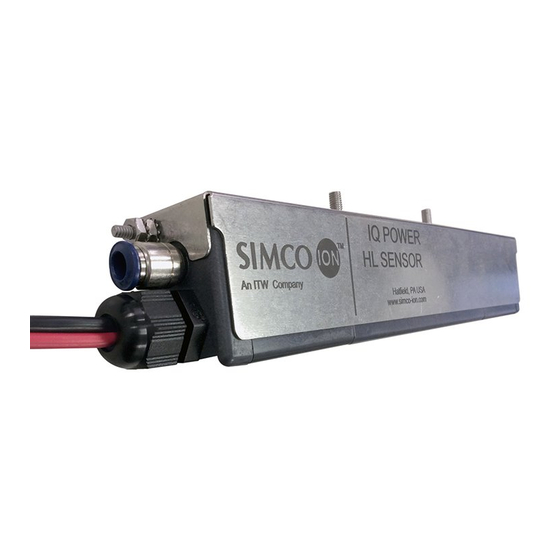
2. DESCRIPTION The IQ Power HL Sensor is an electrostatic field measuring device packaged with a small form-factor. This makes the sensor suitable for use in plastic film and web processing applications. It can monitor processed materials for the presence, polarity and intensity of electrostatic charges. -
Page 6: Specifications
3. SPECIFICATIONS Input Power 24 VDC, 30 mA nominal via (user supplied) Intrinsic Safety Barriers (ref. Control Drawing Input Connection 5150010) Input Cable Lengths 30 ft (9.1m) (for minimizing dust, dirt and contamination in probe aperture only) 1 to 2.5 psi (7 to 17 kPa) nominal operating pressure Input Purge Gas 5 psi (35 kPa) max operating pressure 0.14 scfm (4 NL/min) per sensor at 1 psi (5 kPA) -
Page 7: Installation
4. INSTALLATION Unpacking Carefully remove all equipment from its carton and inspect contents: • Check that details on packing slip correspond to details of product received. • Check that equipment is free from damage. • If any damage has occurred during shipment, notify local carrier at once. A report should also be forwarded to Simco-Ion, 2257 North Penn Road, Hatfield, PA 19440. See Section 9 of this manual for Return Shipment information. Mechanical Installation NOTE –... - Page 8 DO NOT mount sensor over a roller or where material to be measured is in contact with any other surface. Nearby metal reduces sensor readings by capturing electric field lines. NOTE – SENSITIVE ELECTRONICS: Risk of equipment damage. Do not install sensor with charged materials present. Sensor must already be connected to system in presence of charged materials.
-
Page 9: Intrinsic Safety Barriers
Figure 2: IQ Power HL Sensor Positioning (downstream of neutralizing bar) Attach sensor assembly using perforated mounting strip and hardware supplied. The perforated strip may be bent or twisted prior to installation, if necessary. See Figures 1 and 2. 6. Secure perforated mounting strip to a machine frame or user supplied mounting means. -
Page 10: Electrical Connections
Electrical Connections Figure 3 IQ Power HL Sensor Control Drawing 5150010 I Q Power HL S enso r 52 01 25 2 Re v. A... - Page 11 NOTE – Turn line voltage power off at IQ Power Control Station before connecting / disconnecting any devices. This is to avoid potential equipment failure and ensure proper digital communication. Ground IQ Power HL Sensor by connecting ground lead between ground terminal on end of sensor assembly and a good electrical machine ground.
-
Page 12: Purge Gas
Connect Sensor Interface to IQ Power system (Control Station) using modular cable according to instructions included with the interface. Purge Gas NOTE – Purge gas or compressed air used with this device MUST be clean and dry. Dirt, water or oil in the purge gas will damage sensor. If the installation location is prone to surface contamination (such as a coating line) the use of purge gas is mandatory to maintain sensor operation. -
Page 13: Set Up
In connecting sensors to a given IQ Power Sensor Interface, sensor numbers may NOT be duplicated. Connecting multiple sensors with the same Sensor Number to an interface will result in unstable operation and corruption of sensor reporting data. Each sensor will light an indicator on the Sensor Interface that corresponds to its Sensor Number. - Page 14 Calibration Date Sensor x: The date sensor “x” was calibrated, where “x” is the sensor number also reports firmware revision in sensor assembly circuit board. Up Time: The amount of time that sensor interface has been up and running. Device Address: The address of Sensor Interface, a number 1 thru 10, used by Control Station to differentiate devices and also used to define association between devices.
-
Page 15: Operation
5. OPERATION NOTE – Before switching on power; ensure units are properly grounded and the Sensor, Isolation Barriers & Sensor Interface are all properly installed. Operation of sensor is controlled through the IQ Power Control Station. In operation, a device icon appears on the IQ Power Control Station Home Page. Tapping on the device icon for the sensor interface or neutralizer enters a page with a tab containing information about each sensor. -
Page 16: Maintenance
6. MAINTENANCE WARNING – Fire Hazard To prevent ignition of flammable or combustible atmospheres, disconnect power before servicing. AVERTISSEMENT - Risque d’incendie Pour éviter l’inflammation d’atmosphères inflammables ou combustibles , débrancher l’alimentation avant l’entretien. Cleaning Clean sensor assembly using a lint-free wiper moistened (but not saturated) with isopropyl alcohol. -
Page 17: Troubleshooting
7. TROUBLESHOOTING NOTE – Only qualified personnel are to perform troubleshooting tasks. Problem Cause Solution Turn on Control Station No supply voltage Change POWER & COMM from Control Station Power indicator connection at Control Station on interface NOT Check wiring for cuts or breaks illuminated Wiring problem between interface... -
Page 18: Parts & Accessories
8. PARTS & ACCESSORIES Part Description Part Number IQ Power HL Sensor 4016501 Perforated Mounting Strip 4750079 Connector Kit (Sensor to Interface) 5051864 Intrinsically Safe Barrier Kit 5051866 Red & Black Cable (for between Barrier and Interface ONLY) 4810324 I Q Power HL S enso r 52 01 25 2 Re v. -
Page 19: Warranty & Service
9. WARRANTY & SERVICE This product has been carefully tested at the factory and is warranted to be free from any defects in materials or workmanship. Simco-Ion will, under this warranty, repair or replace any equipment that proves, upon our examination, to have become defective within one year from the date of purchase. - Page 20 Simco-Ion 2257 North Penn Road Hatfield, PA 19440 (215) 822-6401 (800) 203-3419 www.simco-ion.com customerservice@simco-ion.com © 2016 Simco-Ion. Printed in the U.S.A. I Q Power HL S enso r 52 01 25 2 Rev . A...
Need help?
Do you have a question about the SIMCO ION IQ Power HL Sensor and is the answer not in the manual?
Questions and answers