
Related Manuals for PCI OAFE-2000


Summary of Contents for PCI OAFE-2000
- Page 1 OAFE-2000 Outdoor Airflow Measurement System Installation, Operation & Maintenance Manual THE SENSEABLE SOLUTION...
-
Page 2: Table Of Contents
OAFE-2000 IO&M Manual TABLE OF CONTENTS 1. INTRODUCTION ..........................1 1.1. Description..........................1 1.2. Basic Operation .......................... 1 1.3. Specifications ..........................2 1.4. Safety ............................2 1.4.1. Electrical Connections ......................2 1.4.2. Static Electricity ........................2 2. AIRFLOW MEASUREMENT STATION .................... 3 ... -
Page 3: Introduction
170 and California Title 24 requirements for verifying the required ventilation rates or air changes per hour. The OAFE-2000 is designed to tackle the challenges of outside airflow measurement which is often low velocity, loaded with particulate, and application specific. The packaged system consists of an integral transmitter and multiple airflow elements, factory mounted and pre-piped in a casing designed for flanged connection to ductwork, control dampers, louvers, etc. -
Page 4: Specifications
OAFE-2000 IO&M Manual This signal is scaled and linearized before being displayed and transmitted out as a 4-20mA or 0- 10VDC signal. The AutoZero option detects and corrects any zero offset caused by large ambient temperature changes. The Temperature Compensation option compensates the flow and velocity signal for density changes caused by variations in the process air temperature. -
Page 5: Airflow Measurement Station
OAFE-2000 IO&M Manual 2. AIRFLOW MEASUREMENT STATION 2.1. Typical Installations ROOFTOP AHU WITH RAIN HOOD ROOFTOP AHU WITH RAIN HOOD EXTERIOR MOUNTED AIRFLOW STATION INTERIOR MOUNTED AIRFLOW STATION OA INTAKE PLENUM OA INTAKE PLENUM (BY OTHERS) (BY OTHERS) RAIN HOOD... -
Page 6: Installation Guidelines For Ducted Applications
OAFE-2000 IO&M Manual 2.2. Installation Guidelines for Ducted Applications The station may be installed in any duct configuration. However, the accuracy of the installation is dependent on the flow conditions in the duct. The minimum installation requirements based upon a uniform velocity profile approaching the duct disturbance for flow rates less than 2,500 fpm are shown below. -
Page 7: Mtse Installation
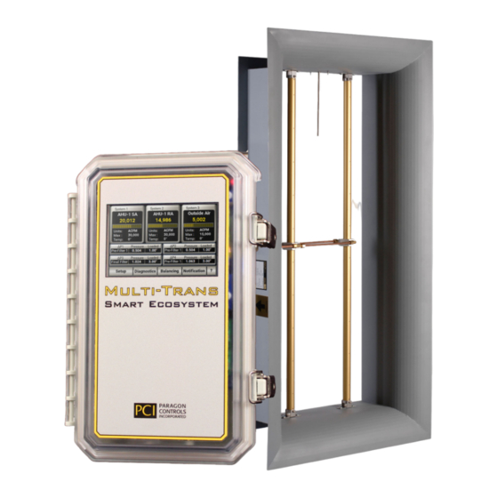
OAFE-2000 IO&M Manual 3. MTSE INSTALLATION The MTSE is rated for either indoor or outdoor installation. It can be mounted near the supply/return/exhaust fans reducing the pneumatic tubing runs. Since the MTSE comes standard in a NEMA 4X Enclosure it can also be mounted in the OA intake where it may be exposed to rain/snow or near cooling coils, providing flexibility in the mounting location. -
Page 8: Electrical Connections
OAFE-2000 IO&M Manual 3.2. Electrical Connections Figure 3.2 – Terminal Block Description J1 – Power In The MTSE can be powered with 24VAC or 24VDC. Allowable range is 20- 28V. Pin 1 on the power supply terminal is the positive leg, however the device is reverse polarity protected. -
Page 9: Common Electrical Connections
OAFE-2000 IO&M Manual 3.2.1. Common Electrical Connections PCI recommends cable should be low capacitance, shielded 24 AWG (minimum) twisted wire for all electrical connections. When connecting multiple MTSE units on a common communication network, connect shielding wires together and connect only one side of the shielding wire to earth ground at the building automation system;... - Page 10 OAFE-2000 IO&M Manual Figure 3.4 – Typical 3 System connection to 24VAC/DC power, 4-20mA loop-powered temperature transmitters, analog receiving devices, or network communication. Paragon Controls Incorporated Revision Level 000...
- Page 11 OAFE-2000 IO&M Manual Figure 3.5 – Typical 3 System connection to 24VAC/DC power, 0-10V three-wire temperature transmitters, analog receiving devices, or network communication. Paragon Controls Incorporated Revision Level 000...
-
Page 12: Pneumatic Connections
OAFE-2000 IO&M Manual 3.3. Pneumatic Connections The MTSE can measure a maximum of five airflow points in up to three systems and monitor up to four ΔP points for a total of 9 sensing points. Two pneumatic plenum-rated signal tubing lines are required to be connected to the MTSE for each sensing point, a high (or Total) and a low (or Static) connection. -
Page 13: Mtse Configurations
OAFE-2000 IO&M Manual 4. MTSE CONFIGURATIONS The MTSE can be configured to measure airflow in up to 3 unique Systems and monitor up to 4 additional differential pressure (ΔP) points up to a total of 9 sensing points. 4.1. Display Overview Shown below is a fully loaded MTSE monitoring (3) independent systems and (4) ΔPs. -
Page 14: System Configurations
OAFE-2000 IO&M Manual 4.2. System Configurations The MTSE can be custom configured to match most applications to measure, sum, and report up to 3 systems and 4 ΔP points for a total of up to 9 sensing points, as described below:... -
Page 15: Display Features
OAFE-2000 IO&M Manual Figure 4.2 – Main Screen for a single system and two systems. 4.3. Display Features 4.3.1. Sensor Data Page Shortcut Touch anywhere within the dashed red box on any of the Main Screen Types (whether it is one system or up to three systems) and the user will be taken to the Sensor Data Page which displays the flow rate and pressure for each individual sensor. -
Page 16: Keypad
OAFE-2000 IO&M Manual 4.3.2. Keypad In most setup menus, it is necessary to enter numeric values for the settings. These values will be entered through a popup keypad, like the one shown below: 1. Parameter Information: Indicates what parameter is currently being entered 2. -
Page 17: Menu Information
OAFE-2000 IO&M Manual 5. MENU INFORMATION 5.1. Levels of Menus The following is a tree view of the available menu pages on the bottom of the Main Screen (see Figure 4.1). Pressing one of these menu buttons loads a separate menu as described below. An icon with a back-arrow key is present in every menu page in the lower left corner of the screen. -
Page 18: Setup Menus
OAFE-2000 IO&M Manual 5.2. Setup Menus In each of these menus, the parameters for Systems 1, 2, and 3 (description of a System can be found in Section 4.2) will be configured. For example, if the user is in the Operating Range Menu the operating range for Systems 1, 2 and 3 will be set in this page. - Page 19 OAFE-2000 IO&M Manual Enter Tagging Information for each system served Toggle Select Area Type either Area or Enter Area or Piezometer Coefficient Piezometer for each system for each system 1. Operating Range Enter Operating Range for each system; Max value that represents 100% of output...
-
Page 20: Operating Range Menu
OAFE-2000 IO&M Manual 5.2.1. Operating Range Menu This menu allows the user to modify the fields shown and described below. This page may look different from your setup if the sensor quantities were only entered for one or two systems. Navigate to this menu from the Main Screen by pressing Setup »... -
Page 21: K-Factor
OAFE-2000 IO&M Manual If an operating range value is entered outside of the allowable minimum/maximum range, the operating range will be set to the maximum value if the new operating range is higher and set to the minimum if the new operating range is lower. -
Page 22: Analog I/O Configuration
OAFE-2000 IO&M Manual FLOW CORRECTION EXAMPLE The balancer is consistently measuring a value of 9,500 CFM, which is 500 CFM less than the 10,000 CFM MTSE value at the time of the balancer measurement. The user would then perform the following math function: Balancer Measurement / MTSE Measurement = K-Factor, so 9,500 CFM / 10,000 CFM = 0.950... -
Page 23: System Filters
OAFE-2000 IO&M Manual 5.2.4. System Filters The System Filters menu allows the user to independently adjust the rolling average calculation by setting the Number of Samples count and the Sampling Interval Time value in seconds for each System. The Number of Samples count range is 1 to 99 sample counts. The adjustment range of the Sample Interval Time is 1 to 65 seconds. -
Page 24: Temperature Compensation & Altitude
OAFE-2000 IO&M Manual Power must be cycled for network changes to take effect. After making changes to the below network parameters, please press the left arrow to return to the main screen to save any changes, then turn off the MTSE at the power switch (S1) for several seconds and then turn the unit back on. -
Page 25: Alarm Options
OAFE-2000 IO&M Manual selected, the temperature value entered in the Fixed box is used. If Variable is selected, an external analog temperature input signal from a temperature sensor is required (see Sections 5.2.3). If Network is selected, the temperature input is obtained through network communications. The temperature value is only displayed on the main screen if the Temperature Source is set to Variable or Network. - Page 26 OAFE-2000 IO&M Manual Enable/Disable Alarms The Alarms can be enabled or disabled by pressing the toggle button beneath the system tagging. Both the high and low alarms will be enabled when a value is entered by touching the respective box and entering a value from the popup keypad.
-
Page 27: Units And Precision
OAFE-2000 IO&M Manual If Lockdown is set too low The MTSE may show flow when the air handling unit or system is off; increase Lockdown. Adjustments should be small as it may take the duration of the lockdown delay and the rolling average in the system filters to catch up before flow is locked to zero. -
Page 28: Δp Settings (Optional)
OAFE-2000 IO&M Manual Measurement Type Allows user to configure the device for Standard Flow, Actual Flow, Standard Velocity, Actual Velocity, or Pressure measurement by toggle button. The selected System Measurement Type limits selection of Engineering Units to only those applicable. Upon changing the Measurement Type, the Engineering Units will start at the first applicable unit shown on the table below. -
Page 29: Diagnostics Menu
OAFE-2000 IO&M Manual ΔP Tagging Selecting this box will provide a keypad popup to allow entry of unique ΔP tagging information. The tagging information will be displayed on the Main Screen and any other place indicating ΔP in the setup menus. -
Page 30: Sensor Data Page
OAFE-2000 IO&M Manual 5.3.1. Sensor Data Page The Sensor Data Page button will navigate to a page displaying measured values for the number of transducers in the MTSE. The transducers are in sequential order from (1) to (10) and display the Fan # tagging, flow, pressure, and status. -
Page 31: System Overview
OAFE-2000 IO&M Manual quantities were incorrectly assigned during factory setup; for example, if there are only 6 sensors in the MTSE however the unit is setup such that the total quantity entered for all systems and OA is 7 sensors, there is no 7... -
Page 32: Factory Defaults
OAFE-2000 IO&M Manual 5.3.3. Factory Defaults The Factory Defaults button allows the user to return all values in the MTSE to the values entered at the Factory. Pressing the “Yes, I am sure.” button from the factory defaults page loads all the parameters saved from the original Factory setup. -
Page 33: Software Update
OAFE-2000 IO&M Manual 5.3.4. Software Update The Software Update page allows users to update the MTSE software in the field when a new microSD (uSD) card has been sent to them. If directed by the Factory to update software and you have received a new uSD card, ensure the POWER SWITCH is in the OFF position, replace the uSD card in the MTSE to update the software;... -
Page 34: Screensaver
1-hour increments. (Values greater than 24 can be entered however the units are then in seconds, not hours. This is for troubleshooting purposes and PCI does not recommend running the autozero valve at that frequency.) Default is 8 hours. -
Page 35: K-Factor
OAFE-2000 IO&M Manual 5.4. K-Factor Page Shortcut Touch the K-Factor Button on the Main Screen and the user will be taken to the K-Factor Page. See Section 5.2.2, K-Factor Section for more details. 5.5. Notification Page All warning messages (with the exception of the transducer zero calibration error shown on the Sensor Data Page) will be displayed on the systems notification page. - Page 36 OAFE-2000 IO&M Manual High Flow Alarm If any system alarm is enabled and the flow for that respective system’s fan exceeds the individual fan high flow alarm value set in the Setup Menu Section 5.2.7 Alarms, then a High Flow Alarm will occur.
-
Page 37: Troubleshooting And Help
OAFE-2000 IO&M Manual 5.6. Troubleshooting and Help Pages On most Diagnostic Menu and Setup Menu pages there will be a “?” located in the lower right-hand corner of the screen. Selecting this button will redirect the user to a page with contextual help for the parameters on the previous page and their function in the MTSE. -
Page 38: Bacnet Protocol Implementation Conformance Statement
OAFE-2000 IO&M Manual ATTACHMENT A BACnet PROTOCOL IMPLEMENTATION CONFORMANCE STATEMENT Paragon Controls Incorporated Revision Level 000... - Page 39 OAFE-2000 IO&M Manual MTSE Unit BACnet Protocol Implementation Conformance Statement Rev 7 3/31/22 BACnet Standardized Device Profile (Annex L): BACnet Application Specific Controller (B-ASC) BACnet Interoperability Building Blocks Supported (Annex K): DS-RP-B DS-RPM-B DS-WP-B DS-WPM-B DM-DDB-B DM-DOB-B DM-DCC-B Segmentation Capability:...
- Page 40 OAFE-2000 IO&M Manual Object Object Name (max 32 Optional Writeable Property Data Data Value Char) Properties Properties Type Description Supported (State Text) DEVICE • Object Name • Object • Description Name • Location • Location • Object Identifier • APDU Timeout •...
- Page 41 OAFE-2000 IO&M Manual Object Object Name (max 32 Optional Writeable Property Data Data Value Char) Properties Properties Type Description Supported (State Text) Analog Value- Differential Pressure 1 • Description REAL Min = 0.0 Alarm Setpoint • Eng Units Max = 99.0...
- Page 42 OAFE-2000 IO&M Manual Object Object Name (max 32 Optional Writeable Property Data Data Value Char) Properties Properties Type Description Supported (State Text) Note: Unit Selection Dependent on Multi State Value-11 Multi State Temperature • Description UNSIGNED 1: F° Value-4 Engineering Units 2: C°...
- Page 43 OAFE-2000 IO&M Manual Object Object Name (max 32 Optional Writeable Property Data Data Value Char) Properties Properties Type Description Supported (State Text) Multi State System 1 Sensor 1 • Description UNSIGNED 1 = Normal Input-11 Status 2 = Alarm 3 = Failure...
-
Page 44: Modbus Software Configuration Parameters
OAFE-2000 IO&M Manual ATTACHMENT B MODBUS SOFTWARE CONFIGURATION PARAMETERS Paragon Controls Incorporated Revision Level 000... - Page 45 OAFE-2000 IO&M Manual MTSE MODBUS SOFTWARE CONFIGURATION PARAMETERS Rev 3 4/13/2021 Communication type: Serial Protocol: RTU - Slave Modbus ID: First device starts at 1 and increments up to 254 Baud Rate: 9.6K, 19.2k, 38.4K(Default), 57.6K & 115.2K Data bits: 8...
- Page 46 OAFE-2000 IO&M Manual Monitoring Variables Object Description Defaul Address Datatype Data Value Description System 1 Total Flow 999999 40301 *Note 1 System 2 Total Flow 999999 40303 *Note 1 System 3 Total Flow 999999 40305 *Note 1 SubSystem Flow 999999...
- Page 47 OAFE-2000 IO&M Manual Commonly Adjusted Variables Object Description Default Address Data Data Value Descriptions type System 1 K-Factor 0.50 2.000 40013 *Note 1 System 2 K-Factor 0.50 2.000 40019 *Note 1 System 3 K-Factor 0.50 2.000 40025 *Note 1 SubSystem K-Factor 0.50...
- Page 48 Paragon Controls Incorporated http://www.paragoncontrols.com Phone 707 / 579-1424...
Need help?
Do you have a question about the OAFE-2000 and is the answer not in the manual?
Questions and answers