Advertisement
PLEASE READ AND FOLLOW ALL INSTRUCTIONS CAREFULLY. FAILURE TO COMPLY
WITH THESE INSTRUCTIONS COULD CAUSE DAMAGE TO THE DEVICE!
OVERVIEW
The Multi-Trans Smart Ecosystem (MTSE) is factory configured so it will
be ready to read airflow and pressure measurements after following this
quick start guide. This guide is intended for field startup of the MTSE only.
The full MTSE Installation, Operation, and Maintenance Manual (IO&M)
can be downloaded from PCI's website at www.paragoncontrols.com.
INSTALLATION CONSIDERATIONS
Power Requirements
Power Consumption
Analog Outputs
Analog Inputs
Supported Protocols
Max communication length
Operating Temperature
Do not exceed ratings. Only qualified personnel should perform
installation. Connection code is located on inside cover.
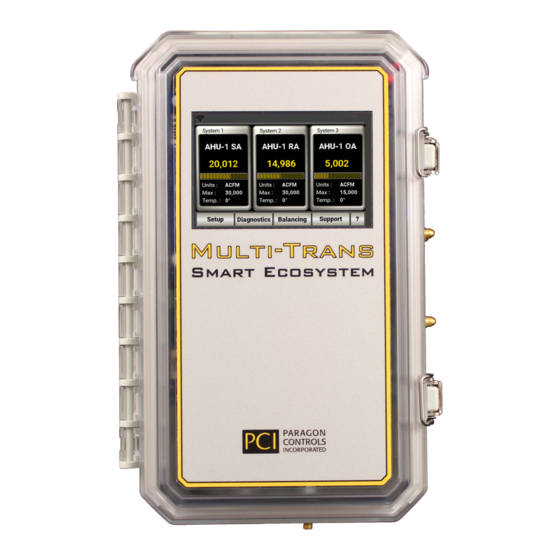
The MTSE can be custom configured to match most applications to measure, sum, and report up to 5 sensing
points in 3 systems (i.e., Supply Air, Return Air, and Outside Air) and 4 additional ΔP points of measurement
(i.e., pre-filter, final filter, coils, etc.) for a total of up to 9 sensing points. Depending on how your MTSE was
ordered, the system quantity and ΔP quantity will change the appearance of the Main Screen. Shown in the
above image is a three-system configuration with no ΔP points of measurement.
INSTALLATION
Before any electrical connections are made, ensure the POWER SWITCH is in the OFF position. The MTSE
is rated for either indoor or outdoor installation. When installed outdoors, do not install the MTSE where the
screen is in direct sunlight. Avoid locations that are subject to high vibration.
Step 1. Open the cover by unlatching the stainless-steel clasps.
Step 2. Ensure the Power Switch is in the OFF position.
Step 3. Install the interface wiring for the electrical connectors as described below. The electrical
connectors have removable terminal blocks for ease of installing the interface wiring. Shielded
24 AWG (min.) twisted-wire cable is recommended for all connections between the MTSE,
temperature transmitter, and network communication. The electrical connection code and
example of electrical connections are shown below.
- For network communication, connect Pins 31 and 32 (J4) to the positive and negative
connectors on the communication device. Ensure that only one side of the shielding wire is
connected to EARTH ground at the building network communication device.
- If a loop powered 4-20mA temperature transmitter (TT) is to be installed for OA, determine
which system is OA from the inside label. For System 1 - connect Pins 71 and 81 (J7 and
J8) on the MTSE to the positive and negative connectors on the TT, respectively; for System
2 – connect Pins 71 and 83; or for System 3 – connect Pins 71 and 85. The TT must be
connected to the correct pins for temperature compensation of corresponding system.
Paragon Controls Incorporated
QUICK START GUIDE
20 - 28VAC/VDC
8.5Watts, 15.3VA Max
(4) 16-bit Analog Outputs
Field Selectable 0-10V & 4-20mA
(4) 12-bit Analog Inputs
Field Selectable 0-5V, 0-10V, & 4-20mA
Modbus RTU Slave, BACnet MS/TP
4000 ft. (EIA-485)
-20°F to 158°F (-29°C to 70°C)
1
Multi-Trans Smart Ecosystem
Revision Level 000
Advertisement
Table of Contents

Subscribe to Our Youtube Channel
Related Manuals for PCI Multi-Trans Smart Ecosystem


Summary of Contents for PCI Multi-Trans Smart Ecosystem
- Page 1 WITH THESE INSTRUCTIONS COULD CAUSE DAMAGE TO THE DEVICE! OVERVIEW The Multi-Trans Smart Ecosystem (MTSE) is factory configured so it will be ready to read airflow and pressure measurements after following this quick start guide. This guide is intended for field startup of the MTSE only.
- Page 2 Multi-Trans Smart Ecosystem Quick Start Guide - Connect Pins 91 and 92 (J9) for System 1 analog process output to the positive and negative connectors on an analog receiving device; connect Pins 93 and 94 for System 2; and connect Pins 95 and 96 for System 3 (if available).
- Page 3 Multi-Trans Smart Ecosystem Quick Start Guide STARTUP Upon power up, the Main Screen will show how the MTSE was configured for the application. If one system was ordered, only System 1 will be visible on the Main Screen, and if two systems were ordered then System 1 and System 2 will show on the screen, etc.
- Page 4 Multi-Trans Smart Ecosystem Quick Start Guide SETUP MENUS Paragon Controls Incorporated Revision Level 000...
Need help?
Do you have a question about the Multi-Trans Smart Ecosystem and is the answer not in the manual?
Questions and answers