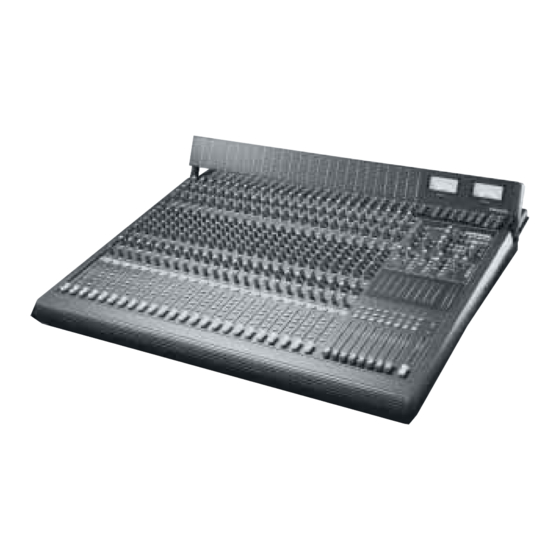
Mackie 16-8 BUS Specifications
Mackie 16-8 bus recording and pa consoles: specifications
Hide thumbs
Also See for 16-8 BUS:
- Owner's manual (64 pages) ,
- Brochure (8 pages) ,
- Hook-up manual (5 pages)
Advertisement
Quick Links
Download this manual
See also:
Owner's Manual
RECORDING AND PA CONSOLES
1. GENERAL CONFIGURA-
TION. The audio mixer shall
have a mainframe capable
of accommodating
16/24/32 inline input/
output channels, with an
optional meter bridge
consisting of 16/24/32
precision LED bargraph
meters to monitor signal
levels in all inline input
channels and VU meters to
monitor control room
source selection, and an
optional separate expander
console capable of accom-
modating an additional 24
inline input/output chan-
nels that shall connect to
the mainframe via 37-pin D-
sub connectors. Note: The
separate expander frame is
not available for the 16•8
mixer. The mainframe shall
also include an overall
master control section, and
provision for directly
mounting 12V gooseneck
type panel lighting via BNC
connectors.
2. POWER SUPPLIES. All
necessary operating volt-
ages for the mainframe
shall be supplied by a two-
rack- space external power
unit that shall connect to
the mainfram via a 7-
conductor cable terminated
in an appropriate connector,
and all necessary operating
voltages for the expander
console shall be supplied by
a two rack space external
power unit that shall con-
nect to the expander frame
via a 7-conductor cable
terminated in an appropriate
connector.
3. CHANNEL INPUTS/
OUTPUT TERMINATIONS.
Each inline input/output
channel shall have the
following inputs and outputs:
a) one balanced
transformerless input for low-
impedance microphone via
3-pin female XLR connector
with gold-plated pins, b) one
balanced/unbalanced
transformerless input for line-
level signals via 3-conductor
1
/
" connector, c) one
4
balanced/unbalanced
transformerless input for
signals from tape, which shall
be switchable globally for 8
channels for a nominal
–10dBV or +4dBU operating
level, d) one unbalanced
line-level direct output via
1
2-conductor
/
" connector,
4
e) one unbalanced output/
input channel patching insert
1
via 3-conductor
/
" connec-
4
tor (tip = send, ring =return).
4. INPUT SWITCHING. Each
inline input/output channel
shall have: a) a mic/line
switch to select signals from
either the mic input or the
line input, b) a flip switch to
determine whether the
mic/line input is fed to the
channel's primary signal path
while the tape input feeds
the Mix-B (Monitor) signal
path, or whether the tape
input feeds the channel's
®
2/6/98
MORE INFORMATION
THESE SPECIFICATIONS
ARE AVAILABLE ON 3.5"
PC & MAC FORMAT DISK IN
POPULAR WORD
PROCESSOR FORMATS
CALL 800/258-6883
FAX 425/487-4337
OUTSIDE THE U.S., CALL
425/487-4333
primary signal path while the
mic/line input feeds the Mix-B
(Monitor) signal path.
5. INPUT LEVEL ADJUSTMENT.
Each inline input/output
channel shall be equipped
with a channel trim control to
adjust the gain of the input
amplifier stage to appropri-
ately match levels presented
to the mic and line inputs.
Advertisement

Related Manuals for Mackie 16-8 BUS


Summary of Contents for Mackie 16-8 BUS
- Page 1 RECORDING AND PA CONSOLES voltages for the expander console shall be supplied by a two rack space external power unit that shall con- nect to the expander frame via a 7-conductor cable terminated in an appropriate connector. 1. GENERAL CONFIGURA- 3.
- Page 2 The shift switch shall select whether the signal as adjusted by its associated rotary controls is sent to AUX 6. DUAL I/O SIGNAL PATHS. outputs 3 and 4, or AUX Each inline input/output outputs 5 and 6, while the channel shall provide pre/post switch determines separate but selectable whether these outputs are...
- Page 3 include faders, routing, solo switching, metering, insert sends with insert returns (patching), and tape outputs from the primary signal path for each of the 8 submasters. and inserted into the Mix-B Overall subgroup level (Monitor) signal path. control shall be provided by Associated switching in the a 100mm fader that incorpo- AUX send section affects the...
-
Page 4: Master Section
L/R Bus, Mix-B (Monitor), tape, or from the external inputs to be used individu- ally or together in any unbalanced transformerless combination to drive the " TS connectors in the respective outputs. An master output section, additional switch shall cause designated Mix-B (Monitor) the control room/studio Outputs L/R. - Page 5 Lo shelving: 80Hz 15dB, console 24-channel frame. MACKIE DESIGNS INC. • 16220 WOOD-RED RD. WOODINVILLE • WA • USA • PHONE TOLLFREE 800/258-6883 FAX 425/487-4337 • OUTSIDE THE U.S., PHONE 425/487-4333 Lo Cut (HPF): 75Hz 18dB/ octave (Tchebechev).
Need help?
Do you have a question about the 16-8 BUS and is the answer not in the manual?
Questions and answers