Table of Contents
Advertisement
Quick Links
Advertisement
Table of Contents

Related Manuals for Delta 22-590X


Summary of Contents for Delta 22-590X
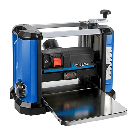
- Page 1 13 inch Portable Planer www.DeltaMachinery.com 22-590X Instruction Manual To reduce the risk of serious injury, thoroughly read and comply with all warnings and instructions in this manual and on product KEEP THIS MANUAL NEAR YOUR PRODUCT FOR EASY REFERENCE AND TO INSTRUCT OTHERS...
-
Page 2: Table Of Contents
PARTS, SERVICE OR WARRANTY ASSISTANCE ..20 USING THE CUTTERHEAD LOCK ........12 FEATURES SPECIFICATIONS The DELTA Model 22-590X is a 13 inch (330mm) Portable ® Planer with a cutting capacity of 1/8 inch (3.2mm). This Planer Supply Voltage: 120 V AC~ can be used on boards up to 13 inch wide (330mm) and 6 inch thick (152mm). - Page 3 FEATURES FIGURE 1 Dust Deflector Wear Table Out-feed Table Cutterhead Height Adjusting Handle In-feed Table Cutterhead Lock Handle Micro Adjustment Depth Stop Knob / Lock Cutterhead Lock Release Main Housing Material Removal Gauge Wrench Storage (Under Table) Indicator Arrow On/Off Switch Dust Collection Base Reset Button...
-
Page 4: Important Safety Instructions
NOT modify and/or use this product for ANY application other than that for which it was designed. If you have any questions or concerns relative to the use of your tool or the contents of this manual, stop using the tool and contact DELTA Customer Service (toll free) 1-800-223-7278. -
Page 5: General Safety Rules
13. Use the right machine. Do not force a machine or an attachment to do a job for which it was not designed. Damage to the machine and/or injury may result. 14. Use recommended accessories. The use of accessories and attachments not recommended by DELTA may cause ®... -
Page 6: Planer Safety Rules
PLANER SAFETY RULES FAILURE TO FOLLOW THESE RULES MAY RESULT IN SERIOUS PERSONAL INJURY. Do not operate this machine until it is completely assembled and installed according to the instructions. A machine incorrectly assembled can cause serious injury. Obtain advice from your supervisor, instructor, or another qualified person if you are not thoroughly familiar with the operation of this machine. -
Page 7: Power Connections
POWER CONNECTIONS POWER SOURCE This planer is equipped with a 15-amp motor for use with a 120-volt, 60-HZ alternating current. See instructions below regarding proper connections for your saw as wired. For voltage, the wiring in a shop is as important as the motor’s rating. A line intended ONLY for lights may not be able to properly carry the current needed for a power tool motor;... -
Page 8: Unpacking
006767 Hardware Bag 2: 006846 006767 FIGURE 2 PACKAGE CONTENTS 22-590X Portable Planer T-Handle T30 Torx Wrench Dust Collection Attachment M6 x 20mm Torx Head Screw (6) Cutterhead Height Adjusting Handle 6.5mm x 16mm x2mm Flat Washer (4) Cutterhead Lock Handle... -
Page 9: Assembly
ASSEMBLY To reduce the risk of injury, turn unit off and disconnect the machine from power source before installing and removing accessories, before adjusting and when making repairs. An accidental start-up can cause injury. ASSEMBLY TOOLS REQUIRED T-Handle T30 Torx Wrench (Supplied) ATTACHING THE CUTTERHEAD LOCK HANDLE... -
Page 10: Preparing For Dust Management
ASSEMBLY PREPARING FOR DUST MANAGEMENT You have two options for dust management. The first is the dust deflector and the second is the dust collection attachment to attach your machine to a dust collector. NOTE: The dust deflector comes factory installed and can be used if the user elects not to use a dust collector system. -
Page 11: Fastening The Planer To Asupporting Surface
ASSEMBLY FASTENING THE PLANER TO A SUPPORTING SURFACE Before operation, secure the planer to the supporting surface. Operate the planer on a flat, level surface. Four mounting holes are provided for mounting the planer to a stand or work surface. These holes are located under the in-feed and out-feed tables (two of which are shown in Figure 9). -
Page 12: Using The Cutterhead Lock
OPERATION USING THE CUTTERHEAD LOCK The cutterhead lock , see Figure 13, prevents the cutterhead depth from being able to change. This helps to eliminate snipe in the board that is being planed. Snipe can also Unlock be eliminated by butting boards end to end and feeding them through the planer. -
Page 13: Recommended Depth Of Cut
OPERATION NOTE: DO NOT exceed the recommended depth of cut for various widths of material, shown in the “RECOMMENDED 1/8 inch DEPTH OF CUT” section below. (3.2mm) DO NOT turn the unit “ON” with the work- 3/32 inch piece in position. (2.4mm) RECOMMENDED DEPTH OF CUT 1/16 inch... -
Page 14: Using The Adjustable Indexing Ring
OPERATION USING THE ADJUSTABLE INDEXING RING The cutterhead height adjusting handle has an adjustment ring Figure 18. The Adjustable Index Ring is best utilized after the initial cut has been made. To use the adjustment ring to make fine adjustments: Once the initial cut has been made and fine tuning is required, measure the thickness of the planed board. -
Page 15: Maintenance/Adjustments
OPERATION SNIPE Snipe is a depression made when an unsupported end of your material drops toward the floor, causing the opposite end to lift up into the cutter head. TO AVOID SNIPE • Feed the workpiece into the planer so it is level and remains flat against the table at all times. •... - Page 16 MAINTENANCE/ADJUSTMENTS Place the magnetized end of the wrench at the center of the knife. Lift the wrench until the knife separates from the pins. Remove the knife. Repeat STEPS 3 through 5 to remove the other two knives. Press down the cutterhead lock release use the supplied wrench to rotate the cutterhead until the lock engages and the next knife is in position...
-
Page 17: Adjusting The In-Feed And Out-Feed Tables
MAINTENANCE/ADJUSTMENTS ADJUSTING THE IN-FEED AND OUT-FEED TABLES Your unit has been factory set with careful table alignment to help eliminate snipe. If your unit loses its adjustment and causes snipe, you can adjust the in-feed and out-feed tables to minimize this condition. -
Page 18: Wear Table And In-Feed/ Out-Feed Table Maintenance
Figure 28, and replace brushes. For proper motor function use ONLY identical replacement brushes. For identical replacement brushes call DELTA Customer Service at (toll free) 1-800-223-7278 or ® e-mail us at www.deltamachinery.com. FIGURE 28... -
Page 19: Troubleshooting
TROUBLESHOOTING For assistance with your machine, visit our website at www.deltamachinery.com for a list of service centers or call DELTA ® Technical Service at (toll free) 1-800-223-7278. FAILURE TO START If your machine fails to start, check to make sure the prongs on the power cord plug are making good contact in the receptacle, and check reset button on power switch housing. -
Page 20: Parts, Service Or Warranty Assistance
24 hours/day. You can also write to us for information at Delta Power Equipment Corporation, 2651 New Cut Road, Spartanburg, SC 29303 - Attention: Technical Service Manager. Be... - Page 21 2651 New Cut Road Spartanburg, SC 29303 (800) 223-7278 www.DeltaMachinery.com ©2022 Delta Power Equipment Corporation DPEC005377 Rev:3 07/27/2022...
Need help?
Do you have a question about the 22-590X and is the answer not in the manual?
Questions and answers