Table of Contents
Advertisement
Service
Manual
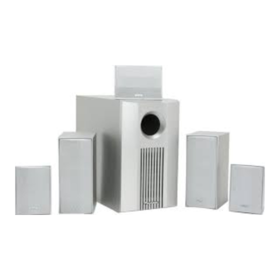
HOME THEATER LOUDSPEAKER SYSTEM
S-FCRW230
THIS MANUAL IS APPLICABLE TO THE FOLLOWING MODELS AND TYPES
TYPE
MODEL
KUXC
S-FCRW230-K
S-FCRW230-S
PIONEER CORPORATION
PIONEER ELECTRONICS SERVICE, INC.
©
PIONEER CORPORATION 2003
COMPONETS
FRONT
KCXC
SUBWOOFER
SATELLITE
1
1
CONTENTS
1. SAFETY INFORMATION ............................................. 2
2. DISASSEMBLY ............................................................ 3
5. PCB CONNECTION DIAGRAM ................................. 10
6. PCB PARTS LIST ...................................................... 13
7. ADJUSTMENT ........................................................... 15
8. PANEL FACILITIES .................................................... 16
9. SPECIFICATIONS ....................................................... 17
4-1, Meguro 1-Chome, Meguro-ku, Tokyo 153-8655, Japan
P.O. Box 1760, Long Beach, CA 90801-1760, U.S.A.
CENTER
REAR
SATELLITE
SATELLITE
2
1
2
2
1
2
ORDER NO.
PET03001
POWER
REMARKS
REQUIREMENT
AC120V
AC120V
Advertisement
Table of Contents

Related Manuals for Pioneer S-FCRW230


Summary of Contents for Pioneer S-FCRW230
-
Page 1: Table Of Contents
6. PCB PARTS LIST ............13 7. ADJUSTMENT ............15 8. PANEL FACILITIES ............ 16 9. SPECIFICATIONS ............17 PIONEER CORPORATION 4-1, Meguro 1-Chome, Meguro-ku, Tokyo 153-8655, Japan PIONEER ELECTRONICS SERVICE, INC. P.O. Box 1760, Long Beach, CA 90801-1760, U.S.A. © PIONEER CORPORATION 2003... -
Page 2: Safety Information
For the latest Test all information, always consult the current PIONEER Service exposed metal surfaces Manual. A subscription to, or additional copies of, PIONEER Service Manual may be obtained at a nominal charge from PIONEER. Also test with plug reversed... -
Page 3: Disassembly
S-FCRW230 2. DISASSEMBLY 2.1 SUBWOOFER 2.2 SATELLITE ¶ Satellite Speakers are provided as assembly units. ¶ POWER AMP SECTION Remove the 8 screws from the power amplifier. Remove the connector lead, etc. ¶ FRONT PANEL The front panel is attached to the cabinet by its bosses applied with adhesive. - Page 4 S-FCRW230 3.2 EXTERIOR SECTION 3.2.1 POWERED SUBWOOFER Parts List Mark No. Description Parts No. 1, 2 Cabinet black PVC (K) 279281 Cabinet silver PVC (S) 279112 Amplifier Assy (HTP-A3) 277374 Front Panel black painted (K) 279296 4, 5 Front Panel silver painted (S)
- Page 5 S-FCRW230 3.3 POWER AMP SECTION NOTES : ¶ Parts marked by “ NSP ” are generally unavailable because they are not in our Master Spare Parts List. ¶ The mark found on some component parts indicates the importance of the safety factor of the part. Therefore, when replacing, be sure to use parts of identical designation.
-
Page 6: Schematic And Pcb Connection Diagrams
S-FCRW230 4. BLOCK DIAGRAM AND SCHEMATIC DIAGRAM 4.1 EXTERIOR SECTION OPERATON Gain Adj Photo ASSY : AWU7761 MAIN Volume Coupler +16v +6 V PC41 TLP621(Y) IC 201 L. P. F. H. P. F. NJM2904M JA201 Line Q201 Buff Buff Level... - Page 7 S-FCRW230 +84v Charge balance and DC feedback Power Speaker Over Voltage Buff Detection C13, C14 - 84v Signal feedback Clip Det. AMP ASSY : AWU7760 DTA124EK Ó Slow ON/OFF 168v Mute Start − Ó G3SBA20L Thermal Detection IRF640 34.5dBv Total Gain...
- Page 8 S-FCRW230 4.2 AMP and OPERATION ASSYS OPERATION ASSY SIGNAL ROUTE : AUDIO SIGNAL • NOTE FOR FUSE REPLACEMENT FOR CONTINUED PROTECTION AGAINST RISK OF FIRE. CAUTION - REPLACE WITH SAME TYPE AND RATINGS ONLY. POWER TRANSFORMER AC POWER CORD KUC : PDG1064...
- Page 9 S-FCRW230 AMP ASSY ADX7356 POWER TRANSFORMER CAUTION : FOR CONTINUED PROTECTION AGAINST RISK OF FIRE. REPLACE ONLY WITH SAME TYPE NO. 491005 FOR IC21, 4910003 FOR IC11, IC12 MFD. BY LITTELFUSE INC.
-
Page 10: Pcb Connection Diagram
S-FCRW230 5. PCB CONNECTION DIAGRAM NOTE FOR PCB DIAGRAMS: 1. Part numbers in PCB diagrams match those in the schematic diagrams. 2. A comparison between the main parts of PCB and schematic diagrams is shown below. Symbol in PCB Symbol in Schematic... - Page 11 S-FCRW230 SIDE A AMP ASSY Q53 Q54 Q51 IC11IC12 IC21 Q21 IC43 VR41 IC44 (ANP7319-C) AC POWER CORD OPERATION ASSY...
- Page 12 S-FCRW230 SIDE B AMP ASSY IC51 IC41 Q201 OPERATION ASSY IC203 IC202 IC201 (ANP7319-C)
-
Page 13: Pcb Parts List
S-FCRW230 6. PCB PARTS LIST NOTES : ¶ Parts marked by “ NSP ” are generally unavailable because they are not in our Master Spare Parts List. ¶ The mark found on some component parts indicates the importance of the safety factor of the part. Therefore, when replacing, be sure to use parts of identical designation. - Page 14 S-FCRW230 Mark Description Parts No. OTHERS CN201 4P CONNECTOR 52147-0410 CABLE ASSY 2P ADX7312 IC11, IC12 PROTECTOR(3A) AEK7015 IC21 PROTECTOR(5A) AEK7019 H1, H2 FUSE CLIP AKR7001 TERMINAL RKC-061 PCB BINDER VEF1040 OPERATION ASSY SEMICONDUCTORS IC201, IC203 NJM2904M D201 AEL7014 D202 MTZJ6.2B...
-
Page 15: Adjustment
S-FCRW230 7. ADJUSTMENT ATTENTION ¶ Don’ t make speaker terminal short circuit during the power supply injection. ¶ Since the PRIMARY part of the AMP ASSY is not insulated, be careful of electric shock. ¶ Be sure to disconnect the power supply cord before touching the AMP ASSY board. -
Page 16: Panel Facilities
S-FCRW230 8. PANEL FACILITIES REAR SECTION 1 POWER indicator Illuminates RED when the power is being supplied. 2 Subwoofer LEVEL knob VOLUME Volume of subwoofer is adjusted with this knob. Turn this LINE LEVEL LEVEL POWER knob clockwise to raise the level. -
Page 17: Specifications
S-FCRW230 9. SPECIFICATIONS FRONT SPEAKERS REAR SPEAKERS Enclosure ..........Closed box type Enclosure ..........Closed box type System ..........2-way loudspeaker System ..........1-way loudspeaker Drive Units Drive Units Tweeter ............3/4” dome Fullrange ............3” cone Midrange ......3” cone magnetically shielded Nominal Impedance ..........
Need help?
Do you have a question about the S-FCRW230 and is the answer not in the manual?
Questions and answers