
Related Manuals for Lucent Technologies CPS4000

Summary of Contents for Lucent Technologies CPS4000
- Page 1 -48V CPS4000/CPS4000 PLUS Cabinet Power System J85500R-1 Product Manual Select Code 167-102-100 Comcode 107222135 Issue 13 December 2000 © 2000 Lucent Technologies...
- Page 3 Select Code 167-102-100 Comcode 107222135 Issue 13 December 2000 Lucent Technologies -48V CPS4000/CPS4000 PLUS Cabinet Power System J85500R-1 Notice: Every effort was made to ensure that the information in this document was complete and accurate at the time of printing.
-
Page 5: Table Of Contents
Lucent Technologies -48V CPS4000/CPS4000 PLUS Cabinet Power System Table of Contents 1 Introduction -48 Volt Cabinet Power System 1 - 1 Overview 1 - 1 Applications 1 - 2 Shelf Design 1 - 2 Configurations 1 - 2 CPS4000 PLUS... - Page 6 Lucent Technologies -48V CPS4000/CPS4000 PLUS Cabinet Power System Remote Access and Control 2 - 8 Power Modules 2 - 9 Overview 2 - 9 ES660 and ES660C Rectifiers 2 - 9 ES680 and ES681 Converters 2 - 9 Ringing Generators...
- Page 7 Lucent Technologies -48V CPS4000/CPS4000 PLUS Cabinet Power System 3 Engineering and Ordering Engineering Information 3 - 1 Introduction 3 - 1 Rectifier Sizing (Non-Redundant Systems) 3 - 1 Rectifier Sizing (Redundant Systems) 3 - 2 Plant Configuration Examples 3 - 3...
- Page 8 Lucent Technologies -48V CPS4000/CPS4000 PLUS Cabinet Power System Interconnecting the Initial and Supplemental Shelves 5 - 5 Installing Batteries 5 - 7 If J85504D-1 Battery Modules Are Installed 5 - 8 If J85504D-1 Battery Modules Are Not Installed 5 - 8 Installing Batteries Below 0°C Temperature...
- Page 9 Lucent Technologies -48V CPS4000/CPS4000 PLUS Cabinet Power System Load Test 5 - 36 LVD Test 5 - 37 J85504D-1 Battery Module Alarm 5 - 37 Adding Rectifiers to a Working Plant 5 - 38 Introduction 5 - 38 Procedure 5 - 38...
- Page 10 Lucent Technologies -48V CPS4000/CPS4000 PLUS Cabinet Power System 7 Alarms, Controls, and Displays Displays 7 - 1 Illustration 7 - 1 Voltage Adjust 7 - 3 Front Panel Test Jacks 7 - 3 Front Panel Meter 7 - 3 LED Test Button...
- Page 11 Lucent Technologies -48V CPS4000/CPS4000 PLUS Cabinet Power System Datalogger Outputs 7 - 20 Overview 7 - 20 LVD/Thermal Management 7 - 21 Introduction 7 - 21 LVD Open 7 - 21 LVD Fail 7 - 21 Probe Fail Alarm 7 - 21...
- Page 13 Lucent Technologies -48V CPS4000/CPS4000 PLUS Cabinet Power System List of Figures Figure 2-1: Block Diagram of -48V CPS With LVD Contactor 2 - 1 Figure 2-2: Block Diagram of -48V CPS Without LVD Contactor 2 - 2 Figure 2-3: CPS Shelf...
- Page 15 Lucent Technologies -48V CPS4000/CPS4000 PLUS Cabinet Power System List of Tables Table 1-A: CPS4000 PLUS Enhancements 1 - 4 Table 2-A: CPS4000 Ringing Generators 2 - 10 Table 2-B: Slope Module Matrix 2 - 17 Table 2-C: Step/Slope Compatibility 2 - 18...
- Page 16 Lucent Technologies -48V CPS4000/CPS4000 PLUS Cabinet Power System Table 3-D: Fuses, Circuit Breakers, and Lugs 3 - 15 Table 3-E: Input Assembly Hardware 3 - 16 Table 3-F: Torque and Tool Information for Input Hardware 3 - 18 Table 3-G: Output Assembly Hardware...
-
Page 17: Introduction
Lucent Technologies -48V CPS4000/CPS4000 PLUS Cabinet Power System Introduction -48 Volt Cabinet Power System Overview The J85500R-1, CPS 4048, -48V Cabinet Power System (CPS) is an extremely flexible power system designed for cabinet applications where space conservation and environmental considerations are critical. -
Page 18: Applications
Lucent Technologies -48V CPS4000/CPS4000 PLUS Cabinet Power System -48 Volt Cabinet Power System, continued Applications CPS fits digital loop carrier, remote switch, fiber in the loop, cable television cabinets, Intelligent Vehicle Highway System (IVHS), Personal Communications Service (PCS), cellular, and customer premises applications. -
Page 19: Cps4000 Plus
Introduction This product manual describes the features and functionality of the existing CPS4000 product line, as well as the enhanced CPS4000 PLUS products. The enhancements to the CPS4000 product are explained in Table 1-A. All other features and functionality of the enhanced CPS PLUS products are identical to the existing product. -
Page 20: 1 - 4 Introduction
Lucent Technologies -48V CPS4000/CPS4000 PLUS Cabinet Power System CPS4000 PLUS, continued Enhancements Table 1-A: CPS4000 PLUS Enhancements CPS4000 PLUS Enhancements Product Description Complete form/fit/function Provides extended life of current CPS4000 product compatibility with deployed base of CPS4000 Operating temperature range of Provides continuous full power operation of the system over -40°C to +75°C (-40°F to 167°F) -
Page 21: Customer Assistance Contacts
Lucent Technologies -48V CPS4000/CPS4000 PLUS Cabinet Power System Customer Assistance Contacts Customer Training Lucent Technologies offers customer training on many Power Systems products. For information call 1-972-284-2163. This number is answered from 8:00 a.m. until 4:30 p.m., Central Time Zone (Zone 6), Monday through Friday. -
Page 22: Warranty Service
For domestic warranty service, contact your Warranty Service Manager (WSM). For international warranty service, contact your sales representative. On-Line Power For Lucent Technologies users logging in from inside the corporate Systems Product firewall, the address of the “Power Systems On-Line Product Manuals” Manuals page is http://www.cic.lucent.com/lineage.html. -
Page 23: Product Description
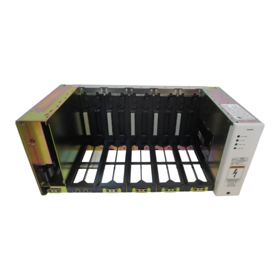
Lucent Technologies -48V CPS4000/CPS4000 PLUS Cabinet Power System Product Description Overview Block Diagrams Figure 2-1 is a basic block diagram of the -48V Cabinet Power System (CPS) configured as an initial shelf or with Low-voltage Disconnect (LVD). Shelf assemblies house and interconnect power modules, a control unit, and a distribution module. -
Page 24: Figure 2-2: Block Diagram Of -48V Cps Without
Lucent Technologies -48V CPS4000/CPS4000 PLUS Cabinet Power System Overview, continued Block Diagrams, Figure 2-2 is a block diagram of the CPS configured as a secondary shelf continued or without Low-voltage Disconnect (LVD). Secondary Secondary Power Bus Output Connector J14 Office... -
Page 25: Shelf Design
Lucent Technologies -48V CPS4000/CPS4000 PLUS Cabinet Power System Shelf Design Features The shelf is available in the 23" standard width and has the following features: • Accepts plug-in modules, such as rectifiers, converters, ringers, and control units, which simplifies plant assembly and repair. -
Page 26: Two-Shelf Plants
Lucent Technologies -48V CPS4000/CPS4000 PLUS Cabinet Power System Shelf Design, continued Two-Shelf Plants In two-shelf plants the system is made up of an initial shelf and a supplemental shelf. This initial/supplemental architecture eliminates redundant equipment in two-shelf plants while offering the full feature set available in single-shelf plants. -
Page 27: Configurations
Lucent Technologies -48V CPS4000/CPS4000 PLUS Cabinet Power System Configurations Introduction The -48V CPS provides the facilities to combine rectifiers, converters, ringing generators, monitor and control units, a low-voltage battery disconnect feature, battery protection circuits, and input and output distribution in a single shelf. The -48V CPS is available in four configurations, which are described below. -
Page 28: Control Units
Lucent Technologies -48V CPS4000/CPS4000 PLUS Cabinet Power System Control Units Overview Included in single-shelf plants or in the initial shelf of two-shelf plants is either: a Monitor and an Alarm Control Unit Control Unit (ES646, ES646B, (ES647) Voltage ES648A, ES648B,... -
Page 29: Es648A/B/Cmcus Only
Lucent Technologies -48V CPS4000/CPS4000 PLUS Cabinet Power System Control Units, continued ES646, ES646B, All Monitor and Control Units (MCU) provide plant monitoring, display ES648A/B/C/BZ and control features, and office alarm outputs. The difference between MCUs MCUs is the alarm scheme and how the alarms are presented to the user. -
Page 30: Alarm Reporting
Lucent Technologies -48V CPS4000/CPS4000 PLUS Cabinet Power System Control Units, continued Alarm Reporting Alarm reporting for the -48V CPS plant is typical of telecommunication battery plants. Alarms are categorized as Power Major (PMJ), indicating service-affecting problems, or Power Minor (PMN), suggesting the problem may become service-affecting if additional problems occur. -
Page 31: Power Modules
Lucent Technologies -48V CPS4000/CPS4000 PLUS Cabinet Power System Power Modules Overview -48V CPS rectifiers and converters are designed specifically for applications where size, weight, wide temperature range, and ease of installation and maintenance are of overriding importance. Switchmode Standby circuit design provides excellent output regulation over... -
Page 32: Ringing Generators
Lucent Technologies -48V CPS4000/CPS4000 PLUS Cabinet Power System Power Modules, continued Ringing Two CPS ringing generators installed in a single-shelf Generators plant provide redundant ringing power. Two-shelf plants offer additional ringing capacity with up to two ringing generators in each shelf. -
Page 33: Figure 2-5: Intershelf Adapter Cables
Lucent Technologies -48V CPS4000/CPS4000 PLUS Cabinet Power System Power Modules, continued Ringing Two CPS ringing generators installed in a single-shelf plant provide Generators, redundant ringing power. Two- and three-shelf plants offer additional continued ringing capacity with up to two ringing generators in each shelf. -
Page 34: Features
Defective fans are easily replaced in the field. • Backward compatible: The CPS4000 PLUS modules are unconditionally compatible with the existing embedded CPS4000 products. The CPS4000 PLUS modules can be added to existing systems to provide partial benefits of the CPS4000 PLUS enhancements. •... - Page 35 Lucent Technologies -48V CPS4000/CPS4000 PLUS Cabinet Power System Power Modules, continued Features, • Output current limit: Power modules provide a constant output continued voltage up to their rated output current, at which point they begin to provide constant current outputs. The maximum output current is inherently limited to less than 110% of the rated output without user adjustment.
- Page 36 Lucent Technologies -48V CPS4000/CPS4000 PLUS Cabinet Power System Power Modules, continued Features, • Plant alarms: Alarm reporting for the -48V CPS plants is typical continued of telecommunication battery plants. Isolated Form-C contact closures provide office alarms on a user-accessible connector.
-
Page 37: Plug-In Distribution Modules
Lucent Technologies -48V CPS4000/CPS4000 PLUS Cabinet Power System Plug-in Distribution Modules Introduction CPS offers three plug-in distribution modules, ES610, ES611, and ES613, which can eliminate the need for separate distribution protection panels and save cabinet space. The distribution modules require 1-inch of space above for wiring. -
Page 38: Module Compatibility
Lucent Technologies -48V CPS4000/CPS4000 PLUS Cabinet Power System Module Compatibility Overview The flexibility of the -48V CPS system is based on the ability to mix physically similar modules in the same shelf assembly. These modules are keyed to prevent incompatible modules from being installed in the same shelf. -
Page 39: Step Vs. Slope Module Compatibility
Lucent Technologies -48V CPS4000/CPS4000 PLUS Cabinet Power System Step vs. Slope Module Compatibility Matching Control In a -48V plant, keying does not prevent mixing control units and LVD/ Units With LVD/ thermal boards with different temperature compensation conventions in Thermal Units the same plant;... -
Page 40: Mixing Step And Slope Units
Lucent Technologies -48V CPS4000/CPS4000 PLUS Cabinet Power System Step vs. Slope Module Compatibility, continued Mixing Step and Table 2-C outlines the results of mixing slope-compensated units and Slope Units step-compensated units in a -48V CPS plant. Table 2-C: Step/Slope Compatibility... -
Page 41: Output Distribution
Lucent Technologies -48V CPS4000/CPS4000 PLUS Cabinet Power System Output Distribution Overview The Output Distribution contains the following: LVD Open LVD Fail • BSR1, which provides connectorized terminations Temp Comp Probe Fail for: – distribution fuse alarms (J9) – battery temperature thermal probes (J10-J13) –... -
Page 42: Lvd/Thermal Management Circuit Pack
ES660 and ES660C rectifiers. This feature compensates the battery float voltage over the temperature range of +25°C to +75°C. CPS4000 PLUS offers an optional extended range slope thermal compensation (EURO Mode). The EURO Mode slope thermal compensation is a switch-selectable option, with the NAFTA Mode as the factory set standard. -
Page 43: Battery Reserve System
Types of Batteries Typically, a CPS plant will use Lucent Technologies 12IR125 batteries. As alternatives, CPS plants may be equipped with other valve-regulated (VR) batteries. Up to four strings of VR-type batteries or equivalent general trade batteries may be connected directly to a 48V CPS shelf. -
Page 44: Specifications
Lucent Technologies -48V CPS4000/CPS4000 PLUS Cabinet Power System Specifications Introduction Tables 2-D through 2-P list the specifications for the 48V CPS4000 and CPS4000 PLUS systems. Electrical Table 2-D: -48V CPS4000/CPS4000 PLUS Electrical Plant Specifications One, two, or three shelves per plant... - Page 45 Lucent Technologies -48V CPS4000/CPS4000 PLUS Cabinet Power System Table 2-D: -48V CPS4000/CPS4000 PLUS Electrical Plant Specifications Plug-in protection and distribution modules: 12 GMT-type fuses; module output limited to 25 amperes or four 3-30A circuit breakers and four GMT-type fuses output limited to 30...
- Page 46 (any output assembly list option from Table 3-A) has been evaluated to the IEC/EN Standards and are CE Marked. Note 7: CPS4000 is a Class A EMC product. In a domestic environment this product may cause radio interference, in which case user may be required to take adequate measures.
-
Page 47: Physical
Lucent Technologies -48V CPS4000/CPS4000 PLUS Cabinet Power System Physical Table 2-E: -48V CPS4000/CPS4000 PLUS Physical Specifications Height: 8.75 inches Width: 3.2 inches Rectifier/Converter Depth: 10.75 inches Weight: 10 pounds (maximum) Height: 8.75 inches Width: 21.5 inches Shelf Depth: 12 inches... -
Page 48: Rectifier Plant
Lucent Technologies -48V CPS4000/CPS4000 PLUS Cabinet Power System Rectifier Plant Table 2-F: Rectifier Plant Specifications CPS4000 CPS4000 PLUS ES660 and ES660C rectifiers; ES660 and ES660C rectifiers; Power Units maximum of five units per maximum of five units per shelf or... - Page 49 Lucent Technologies -48V CPS4000/CPS4000 PLUS Cabinet Power System Table 2-F: Rectifier Plant Specifications CPS4000 CPS4000 PLUS Boost Voltage 58.1Vdc (using ES660C rectifier) Efficiency 86% typical 88.5% (using ES660C rectifier) Output Voltage ±0.5% ±0.5% Regulation Output Noise: Wideband Noise 100 millivolts peak to peak...
-
Page 50: Rectifier-Ringer Plant
Lucent Technologies -48V CPS4000/CPS4000 PLUS Cabinet Power System Rectifier-Ringer Plant Table 2-G: Rectifier-Ringer Plant Specifications ES660, ES660C rectifiers; maximum of four per shelf or nine per plant (limited by LVD rating) Power Units ES620, ES620B, ES621, ES621A, ES621B, or ES622C ringers;... -
Page 51: Rectifier-Converter Plant
MCU: ES646, ES646B, ES648A, ES648B, ES648C, ES648BZ Control Unit ACU: ES647 The CPS4000 primary bus output current capacity is reduced by 12.5 amperes for each active converter installed. Primary Bus Output The CPS4000 PLUS primary bus output current capacity is reduced by 15 amperes for each active converter installed. -
Page 52: Converter Plant
Lucent Technologies -48V CPS4000/CPS4000 PLUS Cabinet Power System Converter Plant Table 2-I: Converter Plant Specifications ES680; maximum of five per shelf or 10 per plant Power Units ES681; maximum of two per shelf or 4 per plant MCU: ES646, ES646B, ES648A, ES648B, ES648C, ES648BZ... -
Page 53: Es660 Rectifier
Lucent Technologies -48V CPS4000/CPS4000 PLUS Cabinet Power System ES660 Rectifier Table 2-J: ES660 Rectifier Specifications Nominal Output Voltage 48/52/54.5Vdc Operating Output Voltage 48-56Vdc (Note 5) Ranges Output Current 0-12.5 amperes Nominal Input Voltage 100/120/200/208/240Vac 90-132Vac Input Voltage Ranges 180-264Vac Operating Frequency Range 47-63Hz 3.3 amperes @ 240Vac (Note 1) -
Page 54: Es660C Rectifier
Lucent Technologies -48V CPS4000/CPS4000 PLUS Cabinet Power System ES660C Rectifier Table 2-K: ES660C Rectifier Specifications Nominal Output Voltage 48/52/54.5Vdc Operating Output Voltage Ranges 48-56Vdc Boost Voltage 58.1Vdc Output Current 0-15 amperes Nominal Input Voltage 100/120/200/208/240Vac 90-132Vac Input Voltage Ranges 180-264Vac 4.0 amperes @ 240Vac (Note 1) -
Page 55: Es680 Converter
Lucent Technologies -48V CPS4000/CPS4000 PLUS Cabinet Power System ES680 Converter Table 2-L: ES680 48/130V Converter Specifications Nominal Output Voltage 132Vdc Output Current 0 - 4 amperes Nominal Input Voltage 48/52/54.5Vac Input Voltage Ranges 38 - 60Vdc 11.3 amperes (Note 1) Input Current 26.0 amperes (Note 2) -
Page 56: Table 2-M: Es681 48/24V Converter Specifications
Lucent Technologies -48V CPS4000/CPS4000 PLUS Cabinet Power System Table 2-M: ES681 48/24V Converter Specifications Nominal Output Voltage 24Vdc Output Current 0 - 25 amperes Nominal Input Voltage 48/52/54.5Vac Input Voltage Ranges 38 - 60Vdc 13.1 amperes (Note 1) Input Current 19.0 amperes (Note 2) -
Page 57: Es620, Es620B, Es621, Es621A, Es621B, Es622B
Lucent Technologies -48V CPS4000/CPS4000 PLUS Cabinet Power System ES620, ES620B, ES621, ES621A, ES621B, ES622B, and ES622C Ringing Generators Table 2-N: ES620, ES620B, ES621, ES621A, ES621B, ES622B, and ES622C Ringing Generator Specifications 75Vrms (ES620B) 80Vrms (ES622B) Nominal Output Voltage 90Vrms (ES621B) -
Page 58: Control Units
Lucent Technologies -48V CPS4000/CPS4000 PLUS Cabinet Power System Control Units Table 2-O: ES646, ES646B, ES647, ES648A, ES648B, ES648C, and ES648BZ Control Unit Specifications 38 - 60Vdc (ES646, ES646B, ES647) Operating Input Voltage Range 19 - 60Vdc (ES648A/B/C/BZ) Input Power 6.0 watts maximum... - Page 59 Lucent Technologies -48V CPS4000/CPS4000 PLUS Cabinet Power System Engineering and Ordering Engineering Information Introduction This section discusses the factors to be considered in determining the number of rectifiers required in both non-redundant and redundant battery plants. Rectifier Sizing In non-redundant systems, the installed rectifier capacity of the battery...
-
Page 60: Figure 3-1: Recharge Factor Vs. Recharge Time
Lucent Technologies -48V CPS4000/CPS4000 PLUS Cabinet Power System Engineering Information, continued Rectifier Sizing In redundant systems, a spare on-line rectifier is included so that the loss (Redundant of any one rectifier will not cause the available plant capacity to fall Systems) below the required minimum installed rectifier capacity. - Page 61 Lucent Technologies -48V CPS4000/CPS4000 PLUS Cabinet Power System Engineering Information, continued Plant To illustrate the relationships between mirc, abh current drains, the Configuration recharge factor, and battery recharge current for non-redundant and Examples redundant systems, consider the following examples. 1. A battery plant is required to provide a load current of 34 amperes, have an 8-hour discharge time (reserve time) and recharge to 95% of battery capacity in 24 hours.
- Page 62 Lucent Technologies -48V CPS4000/CPS4000 PLUS Cabinet Power System Engineering Information, continued Battery Sizing Batteries having different output current capacities should not be mixed Considerations in the same battery plant. Figure 3-1 illustrates several general guidelines for choosing the recharge factor.
- Page 63 Lucent Technologies -48V CPS4000/CPS4000 PLUS Cabinet Power System Ordering Information List Numbers The -48V CPS plant is ordered by List (L) numbers. The -48V CPS plant has four main configurations: • List 1 provides a dual dc output CPS shelf with a primary output of 48 volts and a secondary output of 24 volts.
-
Page 64: Table 3-A: -48V Cps Ordering Information
Lucent Technologies -48V CPS4000/CPS4000 PLUS Cabinet Power System Ordering Information, continued -48V Cabinet Power System Table 3-A: -48V CPS Ordering Information List No. Description -48V chassis assemblies; one is always required per shelf. Each chassis assembly provides five equipment unit slots arranged for ES series power units and distribution modules. Lists 1-4 provide keying functions to prevent insertion of incompatible power units. - Page 65 Lucent Technologies -48V CPS4000/CPS4000 PLUS Cabinet Power System Table 3-A: -48V CPS Ordering Information List No. Description Output 1: -48Vdc, 75 amperes maximum (using ES660C rectifiers only) Output 2: none Arranged for the following apparatus codes: ES660 and ES660C 48V rectifier...
- Page 66 Lucent Technologies -48V CPS4000/CPS4000 PLUS Cabinet Power System Table 3-A: -48V CPS Ordering Information List No. Description AC input assembly (initial shelf) wired for and equipped with one 200-240Vac feed common to all five equipment unit slots for installation with ac wiring run in conduit.
- Page 67 Lucent Technologies -48V CPS4000/CPS4000 PLUS Cabinet Power System Ordering Information, continued Table 3-A Notes 1. These tables describe the arrangement of the chassis assemblies. List 1: 48V Primary Output, 24V Secondary Output (See Note 2) Slot 1 Slot 2 Slot 3...
- Page 68 Lucent Technologies -48V CPS4000/CPS4000 PLUS Cabinet Power System Ordering Information, continued Table 3-A Notes, 2. Shelf assemblies (Lists 1 - 4) provide keying functions to prevent continued insertion of incompatible power units. Select the appropriate list for your application. 3. Input assemblies (Lists 21 - 26) provide connection points for ac input to rectifiers, office alarm outputs, intershelf jumper, and control unit plug-in slot.
- Page 69 Lucent Technologies -48V CPS4000/CPS4000 PLUS Cabinet Power System Ordering Information, continued Table 3-A Notes, 9. Distribution modules provide load protection as follows: for 48V continued loads, 25 amperes/ES610 and 30 amperes/ES611; the ES613 provides load protection for ringer loads. The ES610 is arranged for twelve (12) 0.25 to 10 ampere telecom type fuses.
- Page 70 Lucent Technologies -48V CPS4000/CPS4000 PLUS Cabinet Power System Ordering Information, continued Table 3-A Notes, 14. The -48V CPS plant can support the following configurations: continued • No redundancy for either output • N+1 redundancy for the primary output; no redundancy for the secondary output •...
-
Page 71: Table 3-B: Configured Systems By Comcode
Lucent Technologies -48V CPS4000/CPS4000 PLUS Cabinet Power System Ordering Information, continued Configured Order configured systems using comcodes from Table 3-B. Systems by Comcode Table 3-B: Configured Systems by Comcode Comcode J-Code Description 48V/24Vshelf, 5 ac feeds, 100A LVD, 601787757 J85500R-1 L-1, 21, 35... -
Page 72: Table 3-C: Cps Plug-In Modules And
Lucent Technologies -48V CPS4000/CPS4000 PLUS Cabinet Power System Ordering Information, continued CPS Plug-in Order rectifiers, converters, other plug-in modules, and miscellaneous Modules and equipment from Table 3-C, which lists the modules and their associated Miscellaneous apparatus codes and comcodes. Equipment... -
Page 73: Table 3-D: Fuses, Circuit Breakers, And Lugs
Lucent Technologies -48V CPS4000/CPS4000 PLUS Cabinet Power System Ordering Information, continued Fuses, Circuit Order fuses, circuit breakers, and lugs from Table 3-D. Breakers, Lugs Table 3-D: Fuses, Circuit Breakers, and Lugs Description Comcode AX1 1/4-ampere GMT type fuse with cover... -
Page 74: Table 3-E: Input Assembly Hardware
Lucent Technologies -48V CPS4000/CPS4000 PLUS Cabinet Power System Ordering Information, continued Input Assembly Order cable assemblies for input, output and office alarm connections Hardware from Table 3-E. The table includes both the Lucent Technologies kit and the commercial equivalent. Table 3-E: Input Assembly Hardware Mating Connection List... - Page 75 Lucent Technologies -48V CPS4000/CPS4000 PLUS Cabinet Power System Table 3-E: Input Assembly Hardware Mating Connection List Connector Function Lucent Technologies Commercial Insulated, double 847439833 Kit provides (4) crimped #8 ring-lug for 10-12 ga insulated lugs. Order 12 AWG wire, T&B...
-
Page 76: Table 3-F: Torque And Tool Information For
Lucent Technologies -48V CPS4000/CPS4000 PLUS Cabinet Power System Table 3-E: Input Assembly Hardware Mating Connection List Connector Function Lucent Technologies Commercial 847415874 Kit provides office alarm plug, strain relief Discrete wire set housing, and retaining clip for equipped with (1) Amp... -
Page 77: Table 3-G: Output Assembly Hardware
Lucent Technologies -48V CPS4000/CPS4000 PLUS Cabinet Power System Ordering Information, continued Output Assembly Hardware Table 3-G: Output Assembly Hardware Mating Connection List Connector Function Lucent Technologies Commercial 847415858 Kit for 6 ga wire For 6 ga: T&B 54205UF provides (5) T&B 54205UF 45°... - Page 78 Lucent Technologies -48V CPS4000/CPS4000 PLUS Cabinet Power System Table 3-G: Output Assembly Hardware Mating Connection List Connector Function Lucent Technologies Commercial 847922177 kit provides (1) Molex Plug 15-foot cable with connector for 39-01-2025 shelf on one end and unterminated Socket Terminal leads on the other end.
-
Page 79: Table 3-H: Torque And Tool Information For
Lucent Technologies -48V CPS4000/CPS4000 PLUS Cabinet Power System Ordering Information, continued Torque and Tool Information for Output Hardware Table 3-H: Torque and Tool Information for Output Hardware Connector Comcode Directions Apply lugs using T&B tool TBM5S; torque 847415858 TB1 fasteners to 65 inch-pounds ±10%. - Page 80 Ordering Information, continued Sample Order The order below is a sample order for a CPS4000 one-shelf -48V CPS plant with five ac inputs, three rectifiers, and one alarm unit. This plant does not have low-voltage disconnect or thermal management. This order does not include spares.
-
Page 81: Table 3-K: Recommended Spares
Lucent Technologies -48V CPS4000/CPS4000 PLUS Cabinet Power System Ordering Information, continued Spare Parts With the exception of a fan failure, the power units are repaired by replacement; therefore, each service area needs one set of spares. Table 3-K contains recommended spare parts for the -48V CPS plant. One each is recommended for each service area. - Page 82 Lucent Technologies -48V CPS4000/CPS4000 PLUS Cabinet Power System Documentation -48V CPS Battery Plant Document Comcode -48V Documentation Package includes: – Assembly and Ordering Drawing J85500R-1 – Wiring Diagram T83196-30 847290384 – Schematic Drawing SD83196-01 – Product Manual Select Code 167-102-100...
- Page 83 Lucent Technologies -48V CPS4000/CPS4000 PLUS Cabinet Power System Safety Safety Statements Please read and follow all safety instructions and warnings before installing, maintaining, or repairing the J85500R-1 power shelf: • The CE Mark demonstrates compliance with the European Union Council Directives for Low Voltage and EMC.
- Page 84 Lucent Technologies -48V CPS4000/CPS4000 PLUS Cabinet Power System Safety Statements, continued • Install only in restricted access areas (dedicated equipment rooms, equipment closets, or the like) in accordance with articles 110-16, 110-17, and 110-18 of the U.S. National Electric Code (NEC), ANSI/NFPA No.
- Page 85 Lucent Technologies -48V CPS4000/CPS4000 PLUS Cabinet Power System Safety Statements, continued • Torque electrical connections to the values specified on labels or in the product documentation. • Battery input cables must be dressed to avoid damage to the conductors (caused by routing around sharp edges or routing in areas where wires could get pinched) and undue stress on the connectors.
- Page 86 Lucent Technologies -48V CPS4000/CPS4000 PLUS Cabinet Power System Safety Statements, continued • In enclosed equipment cabinets, the CPS mounting framework must be connected directly to the cabinet ac service ground bus. For applications in huts, vaults, and central offices, the CPS mounting framework must be connected to the system integrated ground grid.
- Page 87 Lucent Technologies -48V CPS4000/CPS4000 PLUS Cabinet Power System Warning Statements and Safety Symbols The symbols may sometimes be accompanied by some type of statement; e.g., “Hazardous voltage/energy inside. Risk of injury. This unit must be accessed only by qualified personnel.”...
- Page 88 Lucent Technologies -48V CPS4000/CPS4000 PLUS Cabinet Power System Warning Statements and Safety Symbols, continued This symbol is used to identify the presence of a hot surface. It may also be accompanied by a statement explaining the hazard. A symbol like this with a lightning...
- Page 89 Lucent Technologies -48V CPS4000/CPS4000 PLUS Cabinet Power System Precautions When working on or using this type of equipment, the following precautions should be noted: • This unit must be installed, serviced, and operated only by skilled and qualified personnel who have the necessary knowledge and practical experience with electrical equipment and who understand the hazards that can arise when working on this type of equipment.
- Page 90 Lucent Technologies -48V CPS4000/CPS4000 PLUS Cabinet Power System Special Installation Instructions German • Installationsanleitung (Installation Instructions) – Eingangsspannung (Voltage): See Table 3-E. – Eingangsstrom (Current): See Table 3-E. – Nennfrequenz (Frequency): 50-60 – Schutzklasse (Protection Class): I – Modellnummer (Model No.): See Table 3-E.
- Page 91 Lucent Technologies -48V CPS4000/CPS4000 PLUS Cabinet Power System Special Installation Instructions, continued Spanish Notas especiales para instalaciones en países de habla hispana • Instrucciones de instalación (Installation Instructions) – Voltaje (Voltage): Vea el vector – Corriente (Current): Vea el vector –...
- Page 93 Lucent Technologies -48V CPS4000/CPS4000 PLUS Cabinet Power System Installation and Testing Preparation Introduction This section outlines the sequence for installing the CPS shelf and plug-in modules and provides a test procedure for verifying the integrity of the installation. Safety Please review all safety warnings in Section 4 before beginning the installation process.
- Page 94 Lucent Technologies -48V CPS4000/CPS4000 PLUS Cabinet Power System Preparation, continued Wiring Guidelines • The commercial ac power input wiring enters the plant on the left (or rear on List 25R or 25RB only). The plant output wiring exits the plant on the right. The alarm wiring to general office alarms exits the plant on the left.
-
Page 95: Figure 5-1: Cps Shelf Dimensions
Lucent Technologies -48V CPS4000/CPS4000 PLUS Cabinet Power System Installing Shelves and Batteries Frame Mounted If -48V CPS shelves, batteries, or battery modules are already mounted Shelves, Batteries, in a cabinet or frame, proceed to “AC Input Wiring.” and Modules One-Shelf Plants To install a one-shelf CPS plant, ensure that adequate space is available for mounting the shelf. - Page 96 Lucent Technologies -48V CPS4000/CPS4000 PLUS Cabinet Power System Installing Shelves and Batteries, continued Multiple-Shelf A multiple-shelf CPS plant is composed of: Plants • an initial shelf, which provides for: – rectifiers – converters or ringing generators – a control unit –...
-
Page 97: Figure 5-2: Alarm, Intershelf, Lvd/Thermal Management
Lucent Technologies -48V CPS4000/CPS4000 PLUS Cabinet Power System Installing Shelves and Batteries, continued Interconnecting the Initial and Supplemental Shelves J15: Output 2 (Secondary) Current Monitor J10-J13: Thermal BSP Board Probe Connectors J14: Ringer or Converter Output Connector J9: Fuse Alarm... - Page 98 Lucent Technologies -48V CPS4000/CPS4000 PLUS Cabinet Power System Installing Shelves and Batteries, continued Interconnecting Interconnecting initial and supplemental shelves to form one plant Initial and requires power connections between TB1, TB2, and TB3 on the initial Supplemental shelf and between TB1 and TB2 on the supplemental shelves.
-
Page 99: Figure 5-3: J85504D-1 Battery Module
Lucent Technologies -48V CPS4000/CPS4000 PLUS Cabinet Power System Installing Shelves and Batteries, continued Installing Batteries Installing Batteries Step Action Verify that the proper batteries have been ordered and received. • To install Lucent Technologies 12IR125 or VR-type batteries, refer to the appropriate product manuals. Follow all safety precautions when installing batteries. - Page 100 Lucent Technologies -48V CPS4000/CPS4000 PLUS Cabinet Power System Installing Shelves and Batteries, continued If J85504D-1 If battery modules are installed, proceed as follows: Battery Modules Are Installed If J85504D-1 Battery Modules Are Installed Step Action Locate the alarm cable (847157674) provided for each battery module.
- Page 101 Lucent Technologies -48V CPS4000/CPS4000 PLUS Cabinet Power System Installing Shelves and Batteries, continued Installing Batteries • Installing cold batteries with temperature probes in ambient Below 0°C temperatures below -10°C may generate a PMN alarm and a Probe Temperature Fail alarm due to a failed temperature probe condition.
- Page 102 Lucent Technologies -48V CPS4000/CPS4000 PLUS Cabinet Power System AC Input Wiring Options There are various options available for input wiring for the -48V CPS shelves: • Separate ac inputs for each power slot with connectors designated as J1 through J5 •...
- Page 103 Lucent Technologies -48V CPS4000/CPS4000 PLUS Cabinet Power System AC Input Wiring, continued Notes • The -48V CPS shelf may be powered from a single branch circuit or from separate branch circuits for each input. • Branch circuits must be protected using fuses or circuit breakers sized as required by the National Electric Code.
-
Page 104: Figure 5-4: Input Assemblies (Left Side Of Cps Shelf)
Lucent Technologies -48V CPS4000/CPS4000 PLUS Cabinet Power System AC Input Wiring, continued Input Assemblies J1-J5 AC Input J1 Powers Slot 1 J1 AC Input J2 Powers Slot 2 Powers Slots 1-5 Etc. ESD Ground Point ESD Ground Point J6 Office Alarm... - Page 105 Lucent Technologies -48V CPS4000/CPS4000 PLUS Cabinet Power System Installing Control Units Introduction A single control unit can control a one-, two-, or three-shelf plant. Procedure Installing Control Units Step Action Determine whether a Monitor and Control Unit or an Alarm Control Unit is to be installed.
- Page 106 Lucent Technologies -48V CPS4000/CPS4000 PLUS Cabinet Power System Office Alarm Wiring Access to Alarms Office alarms may be accessed on J6, located on the left side of the shelf adjacent to the control unit. These alarms are provided on Form-C, or...
-
Page 107: Figure 5-5: Cps Plug-In Modules
Lucent Technologies -48V CPS4000/CPS4000 PLUS Cabinet Power System Plug-in Modules Introduction Refer to Figure 5-5 and the illustration in the following procedure for the locations of the plug-in modules (power units). Control Unit SW2* SW201 Power Unit Slots SW440 BSR1... - Page 108 Lucent Technologies -48V CPS4000/CPS4000 PLUS Cabinet Power System Plug-In Modules, continued Procedure Plug-in Modules Step Action Verify that the proper modules have been ordered and received. Disconnect the power to the shelf by turning the ac service circuit breakers Off.
- Page 109 Lucent Technologies -48V CPS4000/CPS4000 PLUS Cabinet Power System Low-Voltage Disconnect (LVD) Function Overview The Low-Voltage Disconnect (LVD) function is pre-set in the factory at 42.5 volts (SW201 switches 1 and 2 in the ON position). For 40.5V Low-Voltage Disconnect, set SW201 switches 1 and 2 to the OFF position.
-
Page 110: Figure 5-6: Output Assemblies (Right Side Of Cps Shelf)
Lucent Technologies -48V CPS4000/CPS4000 PLUS Cabinet Power System DC Distribution Wiring Output Assemblies J10-J13 Thermal J14: Output 2 (Secondary) Probe Connectors List 1: 24V List 2: 130V J15 Output 2 (Secondary) List 3: Ringer Current Monitor List 4: Not Used... - Page 111 Lucent Technologies -48V CPS4000/CPS4000 PLUS Cabinet Power System DC Distribution Wiring, continued Kits Kits providing the cables and hardware needed for this procedure are listed in Section 3, Engineering and Ordering. Procedure Note: When running dc output cables, pair the positive and negative conductors over as much of their length as possible to minimize loop areas for EMI considerations.
- Page 112 Lucent Technologies -48V CPS4000/CPS4000 PLUS Cabinet Power System Distribution Modules Introduction If you are using a plug-in distribution module, refer to the appropriate paragraph (ES610, ES611, ES613) in this section. Warning Installing fuses or circuit breakers not specified for use in these distribution modules may result in injury to service personnel or equipment damage.
-
Page 113: Figure 5-7: Es610 Distribution Module Wiring
Lucent Technologies -48V CPS4000/CPS4000 PLUS Cabinet Power System Distribution Modules, continued ES610 The ES610 plug-in distribution module provides up to twelve GMT type telecom fuses ranging in rating from 1/4 to 10 amperes. Twelve load and return wire termination slots are provided with each module. The total output current of each module is limited to 25 amperes. -
Page 114: Figure 5-8: Es611 Distribution Module Wiring
Lucent Technologies -48V CPS4000/CPS4000 PLUS Cabinet Power System Distribution Modules, continued ES611 The ES611 plug-in distribution module provides up to four circuit breakers ranging in rating from 3 to 30 amperes and two GMT type telecom fuses ranging in rating from 1/4 to 10 amperes. Six load and return wire termination slots are provided with each module. -
Page 115: Figure 5-9: Es613 Distribution Module Wiring
Lucent Technologies -48V CPS4000/CPS4000 PLUS Cabinet Power System Distribution Modules, continued ES613 The ES613 plug-in distribution module provides up to twelve GMT type telecom fuses ranging in rating from 1/4 to 10 amperes. All outputs are secondary 100V protected outputs from the ringing generators and are fully front accessible via terminal block connections. - Page 116 Lucent Technologies -48V CPS4000/CPS4000 PLUS Cabinet Power System Initial Start-up and Test Checklist Refer to Section 7 and the Glossary for a description of the parameters cited in this section. • Verify that all ac service circuit breakers are Off or ac fuses are removed.
- Page 117 Lucent Technologies -48V CPS4000/CPS4000 PLUS Cabinet Power System Initial Start-up and Test, continued Power Units Power Units Step Action Turn the ac service circuit breakers On. Seat each rectifier and/or converter using the 3/16-inch Allen wrench, turning the mounting screw clockwise. Verify that the fan operates on the rectifier or converter.
- Page 118 Lucent Technologies -48V CPS4000/CPS4000 PLUS Cabinet Power System Initial Start-up and Test, continued LED Test LED Test Step Action If installed, press the LED Test pushbutton on the MCU (ES646, ES646B, ES648A/B/C/BZ). Verify that all LEDs and meter segments are illuminated while the switch is depressed.
- Page 119 Reinstall the thermal probes, if provided, to J10-J13 on the connector board. If the temperature sensed by any probe is above the nominal temperature setting (25°C for CPS4000 or CPS4000 PLUS using NAFTA temperature compensation or 20°C for CPS4000 PLUS using EURO temperature...
- Page 120 Lucent Technologies -48V CPS4000/CPS4000 PLUS Cabinet Power System Initial Start-up and Test, continued High Voltage Note: Batteries may need to be removed from the circuit for this Shutdown Test test. High Voltage Shutdown Test Step Action Using the V Adj encoder, slowly increase the plant voltage until the rectifier shuts down and the Alarm LED lights;...
- Page 121 Lucent Technologies -48V CPS4000/CPS4000 PLUS Cabinet Power System Initial Start-up and Test, continued Boost Mode This feature is only available when the ES648 control unit is installed with ES660C Rectifiers. Boost Mode Step Action Verify that all rectifiers are ES660C.
- Page 122 Lucent Technologies -48V CPS4000/CPS4000 PLUS Cabinet Power System Initial Start-up and Test, continued Self-Diagnostics Before running the self-diagnostics on the ES646 and ES648 control units, determine whether you want to exercise only the Alarm LEDs or if you want to test both the LEDs and the office alarm relays. With SW1-position 6 closed (default), the office alarms are not affected by the self-diagnostics.
- Page 123 Lucent Technologies -48V CPS4000/CPS4000 PLUS Cabinet Power System Initial Start-up and Test, continued Rectifier on Standby (1) Rectifier on Standby (1) Step Action Simulate a rectifier alarm by placing one rectifier in standby. Verify that the PMN LED lights on the control unit.
- Page 124 Lucent Technologies -48V CPS4000/CPS4000 PLUS Cabinet Power System Initial Start-up and Test, continued AC Fail (1) AC Fail (1) Step Action For systems with one ac feed per rectifier, turn one input circuit breaker Off. Verify: • PMN and AC Fail LEDs light on the [ES646, ES646B, or ES648] control unit •...
- Page 125 Lucent Technologies -48V CPS4000/CPS4000 PLUS Cabinet Power System Initial Start-up and Test, continued Converter on For rectifier-converter or converter-only plants, repeat these tests for the Standby (1) installed converters. Converter on Standby (1) Step Action Place one converter in standby.
- Page 126 Lucent Technologies -48V CPS4000/CPS4000 PLUS Cabinet Power System Initial Start-up and Test, continued Battery on Note: Disconnect batteries or remove the LVD board for this test. Discharge Battery on Discharge Step Action Disconnect batteries or remove the LVD board. If the system contains an ES648 control unit, disable the Boost Mode feature.
- Page 127 Lucent Technologies -48V CPS4000/CPS4000 PLUS Cabinet Power System Initial Start-up and Test, continued Distribution Fuse Alarm Distribution Fuse Alarm Step Action Simulate a distribution fuse alarm by placing a clip lead between J9 pins 1 and 2 to simulate a primary output fuse alarm or between J14 pins 1 and 2 to simulate a secondary output fuse alarm.
- Page 128 Lucent Technologies -48V CPS4000/CPS4000 PLUS Cabinet Power System Initial Start-up and Test, continued Test Thermal Test the thermal management probe (if ordered) using the following Management procedure: Probe Test Thermal Management Probe Step Action Locate the exposed pins on the rear of a thermal probe and short them together.
- Page 129 Lucent Technologies -48V CPS4000/CPS4000 PLUS Cabinet Power System Initial Start-up and Test, continued LVD Test LVD Test Step Action To simulate a failed low-voltage disconnect contactor: Remove modules in slots 4 and 5 (right-most slots) in the CPS initial shelf.
- Page 130 Lucent Technologies -48V CPS4000/CPS4000 PLUS Cabinet Power System Adding Rectifiers to a Working Plant Introduction Rectifiers and converters may be added with input power applied. However, the On/Standby switch on the unit added must be in the Standby position. Procedure...
- Page 131 Lucent Technologies -48V CPS4000/CPS4000 PLUS Cabinet Power System Installing an Additional Battery String Adding To An To install an additional battery string in an existing -48V battery module Existing Battery or to add an additional battery string to a working -48V CPS plant, refer Module or to the appropriate battery product manual.
- Page 132 Lucent Technologies -48V CPS4000/CPS4000 PLUS Cabinet Power System Installing Output Distribution Circuit Breakers In Working Plants To install circuit breakers for loads being added to a working plant, follow this procedure: Installing Output Distribution Circuit Breakers in Working Plants Step Action Verify that each circuit breaker is Off prior to installation.
- Page 133 Ports The ES648 control unit provides remote access ports that can be used in different ways: • With a Lucent Technologies proprietary modem that plugs into the control unit card, i.e., the Internal Modem – Circuit Pack EMC1 (ES648BZ) •...
- Page 134 An option is available to use the EasyView Software program for viewing remote access and control functions of the ES648 control unit. Contact a local Lucent Technologies sales representative to download a free copy of the EasyView Software program. User Interface The ES648 control unit may be accessed remotely from a modem or terminal device.
-
Page 135: Figure 6-1: Es648 Remote Access Connections
Lucent Technologies -48V CPS4000/CPS4000 PLUS Cabinet Power System Making the Connections Introduction The Internal Modem connection on the EMC1 circuit pack uses an RJ11 connector for connection to a phone line. The ES648BZ control unit has a Internal Modem circuit pack, EMC1, factory installed and tested. - Page 136 Lucent Technologies -48V CPS4000/CPS4000 PLUS Cabinet Power System Port Settings Introduction This section describes the communication port settings for the internal modem, external modem, RS-232 terminal, and RS-485 terminal ports. Internal and The control unit communicates with the internal modem and an external External Modem modem at the same communication settings.
- Page 137 Lucent Technologies -48V CPS4000/CPS4000 PLUS Cabinet Power System Logging In to the System Procedure This section describes how to log into the system. Obtaining an “Enter Password” Prompt Step Action • From a modem: Dial into the control unit and wait for the modem to connect.
-
Page 138: Table 6-A: Objects Supported For Remote Access
Lucent Technologies -48V CPS4000/CPS4000 PLUS Cabinet Power System T1.317 Command Language Introduction The command language is based on the T1.317 standard. The T1.317 standard has been adapted to the needs of a small plant control unit. This section describes the command line log-in sequence as well as commands, objects and attributes used to access measurements, configuration, and control parameters in the control unit. - Page 139 Lucent Technologies -48V CPS4000/CPS4000 PLUS Cabinet Power System T1.317 Command Language, continued Object-Attribute The T1.317 standard provides access to system measurements, Pairs configuration, and control through attributes. Each measurement, configuration, or control parameter is uniquely identified by an object-attribute pair. For example, the object-attribute pair “dc1,vdc”...
-
Page 140: Table 6-B: Object-Attribute Pairs - Related Commands
Lucent Technologies -48V CPS4000/CPS4000 PLUS Cabinet Power System T1.317 Command Language, continued Table 6-B: Object-Attribute Pairs – Related Commands Obj,attr Description Type Range of Values Lucent ES648 ps1,des Power system description text control unit ps1,sid Site ID text up to 15 characters... -
Page 141: Table 6-C: Command Descriptions
Lucent Technologies -48V CPS4000/CPS4000 PLUS Cabinet Power System Commands Introduction This section describes each of the remote access commands supported by this control unit. Command Table 6-C lists the syntax and description of the commands. Note that Descriptions all commands are case sensitive. - Page 142 Lucent Technologies -48V CPS4000/CPS4000 PLUS Cabinet Power System Table 6-C: Command Descriptions Command Syntax Description pas* Change pas t,“password”, Changes either the user or super-user password. The *You must passwords “password” password is sent twice in order to avoid mistakes. The be logged in where: “t”...
-
Page 143: Table 6-D: Alarm Messages
Lucent Technologies -48V CPS4000/CPS4000 PLUS Cabinet Power System Alarm Messages Descriptions Table 6-D lists the available alarm messages and a brief description of each. Table 6-D: Alarm Messages Alarm Message Description No alarms No alarms are active in the system... - Page 144 Lucent Technologies -48V CPS4000/CPS4000 PLUS Cabinet Power System Dial-out On Alarm Overview This section describes the configuration parameters and the algorithm used for dial-out. By default, the control unit is configured not to dial-out at all. It can be configured to dial-out to a primary phone number or an alternate phone number.
- Page 145 Lucent Technologies -48V CPS4000/CPS4000 PLUS Cabinet Power System External Equipment Control and Alarm Input and Alarm • Applies to the ES648A/B/C/BZ control unit only. Refer to Table 7-I Features for external equipment input and alarm connections to the ES648. •...
- Page 147 Lucent Technologies -48V CPS4000/CPS4000 PLUS Cabinet Power System Alarms, Controls, and Displays Displays Illustration Figure 7-1 shows the displays of the alarm control unit, monitor and control unit, ringing generator (ringer), rectifier and converter (same display), distribution unit, and output wiring (low-voltage disconnect/...
-
Page 148: Figure 7-1: Module Displays
Lucent Technologies -48V CPS4000/CPS4000 PLUS Cabinet Power System Displays, continued Voltage Test Standby Current Standby Alarm Alarm Thermal Alarm Normal Normal Fail V Adj V Adj Test Alarm Monitor and Ringing Generator Rectifier (ES620, ES620B, (ES660, ES660C) Control Unit Control Unit... - Page 149 Lucent Technologies -48V CPS4000/CPS4000 PLUS Cabinet Power System Displays, continued Voltage Adjust The V Adj feature on the faceplate of the control units allows users to adjust the rectifier output voltage. • The ES646, ES646B, and ES647 have an adjustment range from 48-57V.
-
Page 150: Table 7-A: Control Unit Features For Primary And Secondary Outputs
Lucent Technologies -48V CPS4000/CPS4000 PLUS Cabinet Power System Control Units Overview The control unit (ES646, ES646B, ES648A/B/C/BZ MCUs or ES643 ACU) administers alarm processing, rectifier On/Standby control, Plant Battery Test, and plant voltage adjustments in the CPS -48V plant. One control unit supports a one-, two-, or three-shelf plant. -
Page 151: Table 7-B: Es646, Es648A, Es648C Sw1 Options
Lucent Technologies -48V CPS4000/CPS4000 PLUS Cabinet Power System Control Units, continued SW1 Options Switch 1 on the control units provides feature selection as outlined in Tables 7-B through 7-D. Switch positions 1 and 2 are not used on any of the control units. -
Page 152: Table 7-D: Es647 Sw1 Options
Lucent Technologies -48V CPS4000/CPS4000 PLUS Cabinet Power System Control Units, continued SW1 Options, continued Table 7-D: ES647 SW1 Options Switch Position Feature Not used Closed BD alarm also generates a PMJ alarm Open BD alarm does not generate a PMJ alarm... -
Page 153: Table 7-F: Es646, Es646B, Es647, And Es648
Lucent Technologies -48V CPS4000/CPS4000 PLUS Cabinet Power System Alarms Adjustable Battery In the event that AC power is lost, the batteries provide power for the on Discharge (BD) load. While the batteries are providing the plant's power, the plant voltage will decrease below the float voltage. The ES646, ES646B, and ES648 MCUs, and the ES647 ACU monitor the plant voltage and issue a Battery on Discharge (BD) alarm. -
Page 154: Table 7-G: Sw201 Lvd Settings
Lucent Technologies -48V CPS4000/CPS4000 PLUS Cabinet Power System Alarms, continued Low-Voltage DIP switches in the BSP2/BSP2C circuit pack permit the user to set the Disconnect (LVD) plant voltage at which the plant load is disconnected from the battery. The disconnect threshold may be set for either 42.5 volts or 40.5 volts. - Page 155 Lucent Technologies -48V CPS4000/CPS4000 PLUS Cabinet Power System Alarms, continued AC Fail Alarm The AC Fail Alarm indicates that ac input power to at least one rectifier is missing or has dropped below the minimum ac voltage for the operating range being used. This alarm results in an isolated transfer contact for the office alarm system.
- Page 156 Lucent Technologies -48V CPS4000/CPS4000 PLUS Cabinet Power System Alarm Processing Overview The control unit processes alarm conditions and presents them to the user as front panel LED indicators and Form-C relay contact closures. The control unit sorts and groups alarm conditions occurring in the CPS plant into two categories, Power Major or Power Minor, based on their impact on plant functions.
- Page 157 Lucent Technologies -48V CPS4000/CPS4000 PLUS Cabinet Power System Alarm Processing, continued Plant Alarm The ES646, ES646B, ES648 MCUs, and the ES647 ACU provide the Conditions and same basic alarm functions; the ES646, ES646B, and ES648 MCUs, Alarm Indications however, offer additional alarm LEDs and a front panel display with a toggle switch to display primary voltage or current;...
-
Page 158: Table 7-H: Plant Alarm Conditions And Indications
Lucent Technologies -48V CPS4000/CPS4000 PLUS Cabinet Power System Alarm Processing, continued Table 7-H: Plant Alarm Conditions and Indications ES646B, ES646 and ES648B, and ES648C ES647 ES648A ES648BZ Power BSP2/ ES610 Alarm Office Office Office Office Unit BSP2C ES611 Condition Alarm... - Page 159 Lucent Technologies -48V CPS4000/CPS4000 PLUS Cabinet Power System Table 7-H: Plant Alarm Conditions and Indications ES646B, ES646 and ES648B, and ES648C ES647 ES648A ES648BZ Power BSP2/ ES610 Alarm Office Office Office Office Unit BSP2C ES611 Condition Alarm Alarm Alarm Alarm...
- Page 160 Lucent Technologies -48V CPS4000/CPS4000 PLUS Cabinet Power System Office Alarm Contacts Introduction These are 60-volt, 0.5-ampere, Form-C or transfer type contacts that allow an installer to connect the control unit to an office alarm system. Each set of isolated contacts consists of a combination of normally open (NO) and normally closed (NC) contacts with one side of each common (C).
-
Page 161: Table 7-I: Office Alarm Assignments (J6)
Lucent Technologies -48V CPS4000/CPS4000 PLUS Cabinet Power System Office Alarm Contacts, continued J6 Pin Table 7-I gives the office alarm pin assignments on J6. Assignments Table 7-I: Office Alarm Assignments (J6) Pin Number Office Alarm PMJ_NO PMJ_C PMJ_NC PMN_NO PMN_C... - Page 162 Lucent Technologies -48V CPS4000/CPS4000 PLUS Cabinet Power System Self-Diagnostics Routine ES646, ES646B, For plants equipped with the ES646, ES646B, or ES648 MCU, a series ES648 MCUs of self diagnostics can be performed. Depressing the LED Test button on the MCU faceplate for more than 6 seconds will initiate the...
- Page 163 Lucent Technologies -48V CPS4000/CPS4000 PLUS Cabinet Power System Plant Battery Test (PBT) Introduction A plant battery test feature is available that allows the user to test battery health and capacity safely without jeopardizing the load; i.e., a user supplied contact closure across J6-29 and J6-30 will reduce the rectifier output voltage set point to approximately 48 volts, which creates a battery on discharge condition.
- Page 164 Lucent Technologies -48V CPS4000/CPS4000 PLUS Cabinet Power System Boost Mode Overview This function recharges the batteries after a BD (Battery on Discharge) event has occurred. The ES648A, ES648B, ES648BZ, and ES648C control units along with the ES660C rectifiers provide the Boost Mode function.
- Page 165 Lucent Technologies -48V CPS4000/CPS4000 PLUS Cabinet Power System External Equipment External The external equipment alarm applies to the ES648 control units only. Equipment Alarm Refer to Table 7-I for external equipment alarm connections to the ES648 control unit. There are no visual or audible alarms on the CPS shelf that are associated with the External Equipment Alarm.
- Page 166 R_RTN (J3-27) is proportional to the plant load current. This voltage multiplied by 25 equals the load current. Each CPS4000 PLUS shelf also has the means to monitor the output current of the secondary output through the use of connector J15, located on the right-hand side of the shelf.
- Page 167 Lucent Technologies -48V CPS4000/CPS4000 PLUS Cabinet Power System LVD/Thermal Management Introduction The display on the Output Wiring module has four LEDs: LVD Open, LVD Fail, Temp Comp, and Probe Fail. An explanation of the circumstances that cause the LEDs to light are given in the following...
-
Page 168: Figure 7-2: -48V Slope Temperature Compensation
Lucent Technologies -48V CPS4000/CPS4000 PLUS Cabinet Power System LVD/Thermal Management, continued NAFTA Algorithm • As temperature rises between 25°C (77°F) and 53°C (127°F), plant voltage is lowered 72mV per degree. At 53°C (127°F) the plant voltage is two volts less than the uncompensated battery float voltage. -
Page 169: Figure 7-3: -48V Slope Temperature Compensation Euro Mode Algorithm
Lucent Technologies -48V CPS4000/CPS4000 PLUS Cabinet Power System LVD/Thermal Management, continued EURO Mode • As temperature rises between 20°C (68°F) and 53°C (127°F), plant Algorithm voltage is lowered 72mV per degree. • As the temperature decreases below 20°C (68°F), the plant voltage increases at the same rate of 72mV per degree until it reaches a maximum of 56.7 volts. - Page 171 Lucent Technologies -48V CPS4000/CPS4000 PLUS Cabinet Power System Maintenance Overview In This Section This section provides field maintenance information and procedures for the power units. Safety Before performing the maintenance procedures, review the safety information in Section 4. Warning AC input voltages are provided to the CPS via multiple input cables.
- Page 172 Lucent Technologies -48V CPS4000/CPS4000 PLUS Cabinet Power System Power Units Introduction With the exception of a fan failure, the power units are repaired by replacement. Fan Maintenance The expected life of the power unit fans at 25°C (77°F) is seven years.
- Page 173 Lucent Technologies -48V CPS4000/CPS4000 PLUS Cabinet Power System Power Units, continued LED Test Use the following test to determine if all front panel LEDs and the LCD display are working properly. LED Test Step Action Press the LED Test button on the MCU face plate.
- Page 175 Lucent Technologies -48V CPS4000/CPS4000 PLUS Cabinet Power System Troubleshooting Overview Safety Review all safety instructions and warnings before troubleshooting the CPS. Warning The modules intended for use in the CPS shelf are not suitable as disconnect means and the spacings of the shelf backplane do not provide adequate spacing to act as a disconnect means.
- Page 176 Lucent Technologies -48V CPS4000/CPS4000 PLUS Cabinet Power System Rectifier Flowchart Start Does Rectifier Deliver Power? Is Any Go to Sheet 2 LED Lit? Is ALM Go to Sheet 3 LED Lit? Is STBY Go to Sheet 2 LED Lit? Is Power...
- Page 177 Lucent Technologies -48V CPS4000/CPS4000 PLUS Cabinet Power System Rectifier Flowchart, continued Do Other Rectifiers Check the AC Source Deliver Power? Is Rectifier Fuse Turn the Input Circuit or Circuit Breaker Breaker On or Replace Fuse on Line? Is Rectifier Fully...
- Page 178 Lucent Technologies -48V CPS4000/CPS4000 PLUS Cabinet Power System Rectifier Flowchart, continued Is There a Fan Remove Obstruction Is TA LED Obstruction? and Restart Rectifier Also Lit? Unplug Rectifier from Shelf Replace Fans Reinstall Rectifier Is the Load Decrease Load or...
- Page 179 Lucent Technologies -48V CPS4000/CPS4000 PLUS Cabinet Power System Converter Flowchart Start Does Converter Deliver Power? Is Any Go to Sheet 2 LED Lit? Is ALM Go to Sheet 3 LED Lit? Is STBY Go to Sheet 2 LED Lit? Is Power...
- Page 180 Lucent Technologies -48V CPS4000/CPS4000 PLUS Cabinet Power System Converter Flowchart, continued Do Other Converters Check the DC Source Deliver Power? Is Converter Fuse Turn the Input Circuit or Circuit Breaker Breaker On or Replace Fuse on Line? Is Converter Fully...
- Page 181 Lucent Technologies -48V CPS4000/CPS4000 PLUS Cabinet Power System Converter Flowchart, continued Is There a Fan Remove Obstruction Is TA LED Obstruction? and Restart Converter Also Lit? Unplug Converter from Shelf Replace Fans Reinstall Converter Is the Load Decrease Load or...
- Page 183 Lucent Technologies -48V CPS4000/CPS4000 PLUS Cabinet Power System Product Warranty A. Seller warrants to Customer only, that: 1. As of the date title to Products passes, Seller will have the right to sell, transfer, and assign such Products and the title conveyed by Seller shall be good;...
- Page 184 Lucent Technologies -48V CPS4000/CPS4000 PLUS Cabinet Power System Warranty Period Repaired Product Product Type New Product or Part* Central Office 24 Months 6 Months Power Equipment** *The Warranty Period for a repaired Product or part thereof is as listed or, in the case of Products under Warranty, is the period listed or the unexpired term of the new Product Warranty Period, whichever is longer.
- Page 185 Lucent Technologies -48V CPS4000/CPS4000 PLUS Cabinet Power System Product to the destination designated by Customer within the Territory. E. The defective or nonconforming Products or parts which are replaced shall become Seller's property. F. If Seller determines that a Product for which warranty service is...
- Page 187 The purchaser of this product should not make any repairs to the EMC1. Repairs are to be made only by Lucent Technologies or its licensees. Unauthorized repairs void registration and warranty. Issue 13 December 2000...
- Page 188 Lucent Technologies -48V CPS4000/CPS4000 PLUS Cabinet Power System This equipment cannot be used on public coin service provided by the telephone company. Connection to Party Line Service is subject to state tariffs. (Contact the state public utility commission, public service commission or corporation commission for information.)
- Page 189 Lucent Technologies -48V CPS4000/CPS4000 PLUS Cabinet Power System Appendix Industry Canada Certification NOTICE: The industry Canada label identifies certified equipment. This certification means that the equipment meets telecommunications network protective, operational and safety requirements as prescribed in the appropriate Terminal Equipment Technical Requirements document(s).
- Page 191 Lucent Technologies -48V CPS4000/CPS4000 PLUS Cabinet Power System Appendix Glossary AC Fail An indicator found in CPS plants, this alarm is issued (yellow LED) when the ac service voltage to a rectifier falls below the normal input operating voltage range.
- Page 192 Lucent Technologies -48V CPS4000/CPS4000 PLUS Cabinet Power System Batt Minor Alarm A signal to the Control Unit indicating that a temperature probe cable is installed, but the probe is missing, a temperature probe has failed, or the LVD circuit has failed but the LVD contactor remains closed.
- Page 193 Lucent Technologies -48V CPS4000/CPS4000 PLUS Cabinet Power System ES622C Ringing Generator; 100VA, 100Vac, 20Hz ES646/ES646B Monitor and Control Unit; for use in -48Vdc CPS battery plants ES647 Alarm Control Unit; for use in -48Vdc CPS battery plants ES648A/B/C Monitor and Control Unit; for use in both -48Vdc and +24Vdc battery...
- Page 194 Lucent Technologies -48V CPS4000/CPS4000 PLUS Cabinet Power System Low-voltage disconnect; preset voltage threshold at which the load is disconnected from the battery voltage in CPS Plants to protect both the batteries and the using equipment. Major Fuse Alarm This red PMJ LED lights to signify that an output distribution circuit (MJF) breaker or fuse has operated due to excessive current.
- Page 195 Lucent Technologies -48V CPS4000/CPS4000 PLUS Cabinet Power System RTAC Regional Technical Assistance Center (1-800-CAL-RTAC) Signal Interface A signal path interface between the control unit and the office alarm Interface that provides customer access to the office alarm and control tie-points on J6 Standby In this mode, the power unit control and alarm circuits are powered;...
Need help?
Do you have a question about the CPS4000 and is the answer not in the manual?
Questions and answers