Table of Contents
Advertisement
PROTECTOWIRE
FireSystems
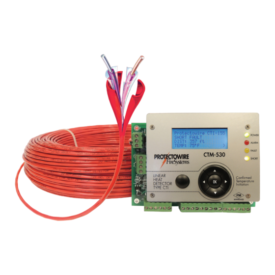
CTM-530 Series Interface Module
with Modbus Over RS-485
Installation and Operation Guide
An ISO 9001 Registered Company
®
PROTECTOWIRE CTI-155
PROTECTOWIRE CTI-155
NORMAL
NORMAL
12:45 PM 4/16/2020
12:45 PM 4/16/2020
CTM-530
CTM-530
LINEAR
LINEAR
HEAT
HEAT
ESC
OK
DETECTOR
ESC
OK
DETECTOR
FM
APPROVED
APPROVED
POWER
POWER
ALARM
ALARM
FAULT
FAULT
SHORT
SHORT
RX
RX
FM
TX
TX
Advertisement
Table of Contents

Related Manuals for Protectowire CTM-530 Series


Summary of Contents for Protectowire CTM-530 Series
- Page 1 POWER 12:45 PM 4/16/2020 12:45 PM 4/16/2020 ALARM ALARM FAULT FAULT CTM-530 CTM-530 SHORT SHORT LINEAR LINEAR HEAT HEAT DETECTOR DETECTOR APPROVED APPROVED CTM-530 Series Interface Module with Modbus Over RS-485 Installation and Operation Guide An ISO 9001 Registered Company...
- Page 2 PROTECTOWIRE ® FireSystems MAN-2006 Last modifi ed 3/26/2021 Contains updates included in Firmware v1.3.5 © 2020 The Protectowire Co., Inc. 60 Washington Street Pembroke, MA 02359 Phone 781-826-3878 • Fax 781-826-2045 E-Mail: pwire@protectowire.com WWW.PROTECTOWIRE.COM CTM-530 Series Interface Module Installation and Operation Guide...
-
Page 3: Table Of Contents
Table of Contents How CTI Technology Works Digital Linear Heat Detection Operation ..................1 CTI Linear Heat Detection Operation ..................... 2 The CTM-530 Interface Module General Information ......................... 4 Description ............................4 Specifi cations ............................ 5 4-20mA Output Information ......................6 Installation and Wiring ........................ - Page 4 Table of Contents Modbus Over RS-485 Operation Guide Descriptions ........................... 33 RS-485 Serial Bus ......................33 Modbus Protocol ....................... 33 CTM-530 Modbus over RS-485 ..................33 Specifi cations ..........................34 Port Specifi cations ......................34 Protocol Specifi cations ....................... 34 Wiring Wiring Description ......................
-
Page 5: How Cti Technology Works
CTI confi rms thermal activation of the Digital Linear Heat Detector before an alarm is initiated thereby re- ducing the incidence of false alarms created by physical damage to the detector. Protectowire CTI Digital Linear Heat Detectors are the only digital linear heat detectors to provide Short Circuit Discrimination. -
Page 6: Cti Linear Heat Detection Operation
This very reliable method of detection has been in use for over 75 years in the fi re protection industry; however the possibility of mechanical damage causing a short circuit does exist. A short caused by mechanical damage will produce a false alarm condition therefore care needs to be taken during installation and design to locate the detector in areas it is least likely to be subjected to physical damage. - Page 7 Figure 4b - When a short occurs at a point along the detectors length an initiating device circuit detects the short and then automatically switches to a thermocouple measurement mode. The shorted portion of the de- tector forms a thermocouple junction which can be measured. The thermocouple measurement represents the current temperature of the shorted portion of detector.
-
Page 8: The Ctm-530 Interface Module
APPROVED General Information The Protectowire CTM-530 is a detection control module that is an interface between a main fire alarm control panel detection circuit or addressable node and Protectowire Type CTI Linear Heat Detector. The module provides one (1) supervised detection circuit that may be field wired for either Class A (Style D) or Class B (Style B) service. -
Page 9: Specifi Cations
Inputs • One initiating device circuit capable of monitoring up to 4000 Feet (1220 Meters) of Protectowire Type CTI Linear Heat Detector. For all CTI type detectors, twisted “T” type extension grade thermocouple wire is required for use as interconnecting wire on the detection circuit. Minimum conductor size is 20AWG (0.812mm), or as require by local code. -
Page 10: 4-20Ma Output Information
4-20mA Output Information Description - The CTM-530 provides wo 4-20mA outputs that allow for monitoring of the module status and active alarm point location reading. These outputs are intended for annunciation purposes only. Module monitoring is intended to be accomplished using the on board supplied dry contacts connected to a listed or approved fi... -
Page 11: Installation And Wiring
GND terminal and COM terminal must be connected to each other. PROTECTOWIRE CTI-155 EARTH GND NORMAL POWER POWER 12-24VDC ALARM 1.6 WATT 11:38am 12/21/2016 FAULT PROTECTOWIRE CTI LINEAR ZB-5 ZONE ZB-5 ZONE HEAT DETECTOR SHORT CTM-530 (CLASS B) PROTECTOWIRE END LINE ® RESISTOR STATUS... -
Page 12: Detector Wiring
Class A (Style D) or Class B (Style B)service. The alarm initiating circuit is capable of operating up to 4000 feet (1220 meters) of Protectowire Type CTI Linear Heat Detector. The CTM-530 initiation circuit is designed to monitor Protectowire Type CTI Linear Heat Detector only and does not support other types of normally open contact alarm initiating devices. -
Page 13: Power Wiring
Installation and Wiring - (continued) Power Wiring - The CTM-530 requires external regulated, uninterruptible DC power. The module pro- vides an internal switch regulator which supports input voltages between 12 to 24 VDC (+10% - 15%) @ 1.6 Watts. To implement remote resetting of the module from the host panel, the supplied power bay be interrupted during the host panels reset sequence. -
Page 14: Confi Guration & Feature Selection
Display, Menus and Navigation Controls - The standard version of the CTM-530 has an integrated LCD display an navigation controls which allow user access to the detectors status information and the setup menu. PROTECTOWIRE CTI-155 NORMAL LCD Status POWER... -
Page 15: Resetting The Detector
ENTER SETUP Password error. PASSWORD: 0000 Retry or press ESC. Password Entry Screen Password Error Screen Use the left and right navigation buttons to select each character and th eup and down navigation buttons to change the character. Once all characters have been entered press the center navigation button labled OK to access the menu. -
Page 16: Detector Type Selection
Protectowire CTI-155 Protectowire CTI-155 EVENT CLEARED NORMAL 9:45AM 4/24/2020 Status Screen Status Screen The display will show an “EVENT CLEARED” message while the detector resets. All outputs should return to normal standby states. Once the reset process has completed the display will return to a normal standby display. -
Page 17: Display Units
Protectowire CTI-220 Protectowire CTI-155 EVENT CLEARED NORMAL 9:45AM 4/24/2020 Reset Screen Status Screen Display Units - The CTM-530 can be confi gured to display measurement information in either US Stan- dard (Temperature = °F, Distance = Feet) or Metric units (Temperature = °C, Distance = Meters). Select a unit type by entering the setup menu and selecting the “4: DISPLAY UNITS”... - Page 18 Class A fi eld wiring arrangement. The procedure is the same for both Class B and A wiring con- fi guration. unless otherwise noted. Where extension wire is not utilized shorts should be placed across the detector terminations on the CTM-530 inputs. CTM-530 Protectowire CTI Linear Heat Detector Protectowire CTI-155 NORMAL...
- Page 19 Step 2 - Place a short across the end (END distance) of the CTI linear heat detector run as depicted in Fig- ure 9 for Class B and as depicted in Figure 10 for Class A. CTM-530 Protectowire CTI Linear Heat Detector AUTO CALIBRATE:...
- Page 20 To calibrate the Alarm Point Location END point SPAN distance enter the setup menu an dselect the “5: APL SETUP” menu item and press the “OK” button. The “APL SETUP:” screen will be displayed. Select the “2: CAL END PT./SPAN” option from the menu and press the “OK” button. The AUTO CALI- BRATE: END Distance message will be displayed.
-
Page 21: Junction Test Bypass
View the current calibration settings by selecting the “3: VIEW CURRENT CAL” option from the APL SETUP menu. The current calibration settings screen is displayed. Line one shows the current Ohms per foot or Ohms per Meter multiplier used to convert resistance to distance. Line two shows the outgoing offset resistance in Ohms which should be equivalent to the outgoing extension wire total resistance. -
Page 22: Time And Date Setup
Time and Date Setup - The CTM-530 features a real time clock with date. Tim is displayed in 12 hour fo- mat and the date is displayed in Mont/Day/Year format. The clock will maintain time and date settings even in the event of complete power failure via a backup battery. To set the time and date enter the setup menu and select the “7: TIME AND DATE”... -
Page 23: Event History
Time and Date - Time and Date not affected Passwords - USER level reset to 1000, TECH level reset to 2000 Cold Junction - Cold junction is not affected Event History - History is cleared Modbus - All Modbus settings reset. Slave ID = 1, Parity 8-E-1, Baud Rate = 19.2Kbps To perform a factory restore enter the setup menu and select the “10: FACTORY RESTORE”... -
Page 24: Cold Junction Test And Offset
Once an event has been selected using the navigation UP/Down buttons, press the “OK” button to view additional information for the selected event. As shown in th screen shots below, event 6, a short fault condi- tion on the channel 1 is selected. EVENT HISTORY: 6: SHORT FAULT CH1 4: TECH LEVEL RESET... -
Page 25: 4-20Ma Output Calibration
4-20mA Outputs Calibration - The CTM-530 features a calibration adjustment for each of the 4-20mA output loops. The outputs are factory calibrated but to achieve the best accuracy a qualifi ed technician can adjust the output levels as required. A calibrated current meter must fi rst be connected to each output before beginning the calibration procedure. -
Page 26: Operation And Testing
Visually inspect the linear heat detector installation and confi rm conformance with the Installation, Op- eration and Maintenance Manual for Protectowire Linear Heat Detectors. Check for any signs of physical damage or wear to the detector and associated installation hardware. -
Page 27: Detection Operation And Testing
Figure - 12 Step 1 - Test Open Circuit Monitoring - At the end of the Protectowire Linear Heat Detector, open the circuit by disconnecting one leg of the detector from the ELR, see Figure 13, or return fi eld terminals, see Figure 14. -
Page 28: Test Short Fault Monitoring
Normal Standby Display Step 2 - Test Short Circuit Monitoring - At the end of the Protectowire Linear Heat Detector, connect a jumper lead across both legs of the detector at the ELR, see Figure 15 or return fi eld terminals, see Figure 16. - Page 29 Any remote device monitoring the CTM-530 status should indicate a supervisory or fault condition depending on how the short monitoring is implemented. Remove the short and reset the interface module to return to a normal standby condition. Protectowire CTI-190 Protectowire CTI-190 SHORT FAULT...
-
Page 30: Testing Alarm Activation With Cti
The thermocouple probe will cause a short circuit in the detection loop and the CTM-530 will fi rst indicate a short circuit fault. Confi rm the temperature of the short fault is properly measured at the CTM-530 being sure both the Out and Return readings are displayed for Class A circuits. Protectowire CTI-190 Protectowire CTI-190 SHORT FAULT... - Page 31 Figures 17 & 18 making sure that the CTI linear heat detector is not exposed to the heat source. The temperature measurement displayed on the CTM-530 should begin to increase in response to the applied heat source. Protectowire CTI-190 Protectowire CTI-190 SHORT FAULT...
-
Page 32: Verify Temperature Measurements
Step 4 - Verify Temperature Measurement - To verify the accuracy of the CTM-530 temperature measure- ments the fi rst junction of a dual junction thermocouple probe must be connected to the input terminal of the CTM-530 or to the test jack in the fi rst zone box as shown in Figure 19. A calibrated test meter is then connected to the second junction of the probe. -
Page 33: Testing Accessories
Model #: HTQIN-316U-12 or equivalent Description: Used for testing splice points using the CTIC splicing terminals Important! - This item is sold by a 3rd party and is not sold by Protectowire. Item #3: Dual Element Probe “T” type, Ungrounded Manufacturer - Omega Engineering http://www.omega.com... - Page 34 All CTM-530 interface modules are factory cal- ibrated; typically fi eld calibration of the CTM module temperature measurements is not required. Please consult with Protectowire technical support and see the CTM-530 manual for complete instructions. CTM-530E Th ermocouple Meter &...
-
Page 35: Hazardous Location Applications (Factory Mutual Only)
9/6/16 DESCRIPTION: Some applications of PROTECTOWIRE CTi type linear heat detection circuits require energy limiting to prevent explosions in areas classified as hazardous locations. One method used to accomplish this “Intrinsic Safety” is to utilize diode shunt barriers. Diode shunt barriers consist of zener diodes with current limiting resistors which “shunt” excess voltage spikes to ground. -
Page 36: Isb Illustration Drawing Il-1622
Page 32... -
Page 37: Descriptions
Modbus Over RS-485 PROTECTOWIRE CTI-155 Operation Guide NORMAL POWER 11:38am 12/21/2016 ALARM FAULT CTM-530 SHORT LINEAR HEAT DETECTOR APPROVED RS-485 Description RS-485 isa standard which describes a physical layer utilized in serial communication. RS-48 allows for installation of inexpensive local network systems and supports multi-drop communication links. Due to its use of differential balanced line signaling oer twisted pair wring, RS-485 can span distances of up to 4,000 feet (1,220 meters) without repeaters. -
Page 38: Specifi Cations
Specifi cations Port Specifi cations • RS-485 Serial Port compatible iwth TIA/EIA-485 specifi cations • Supports Half Duplex Mode (2 wire) • Baud Rates Supported, 9.6K, 19.2K, 57.6K, 115.2K • Network Bus Load, 1/8th Load • Biasing, None • Wiring method, Two wire with common via module supply common Protocol Information •... -
Page 39: Wiring
(+) and receive (-) terminals respectively. The module does not currently support full duplex operation. Wiring Diagram - Figure 1 Modbus over RS-485 is intended to provide ancil- PROTECTOWIRE CTI-155 lary information. Each unit NORMAL POWER MUST be monitored by a... -
Page 40: Confi Guration Settings
Display, Menus and Navigation Controls - The standard version of the CTM-530 has an integrated LCD display and navigation controls which allow user access to the detectors status information and the setup menu. For full instructions on the menu access and settings please see the CTM-530 user manual. PROTECTOWIRE CTI-155 NORMAL LCD Status... -
Page 41: Setting The Slave Address
Use the down navigation key to scroll to the “MODBUS” menu item and then press the center button to enter the Modbus menu. SETUP: TECH MODBUS: 14: LOOP 2 CAL 1: SLAVE ADDRESS > 15: LANGUAGE 2: PARITY 16: MODBUS >... -
Page 42: Setting The Baud Rate
Setting the Baud Rate - Once in the “MODBUS” menu use the UP/DOWN navigation keys to select the “Baud Rate” menu item. Depress the center navigation button to enter the Baud Rate menu. MODBUS BAUD: MODBUS PARITY: 1: 9600 Settings Saved. 2: 19200 >... -
Page 43: Module Status
Module Status - The CTM-530 Status is available from a single 16 bit Modbus holding register at protocol address 40001. Each bit of the holding register represents a function status of the module. The status bits are arranged so monitoring only the 3 least signifi cant bits provides the priority status of the module. The priority status bit states are Normal (All bits zero), Fault (Bit zero active), Short (Bit 1 active) and Alarm (Bit 2 Active). -
Page 44: Temperature Readings
Temperature Readings - The CTM-530 temperature readings are available as a single integer value at Mod- bus holding register 40002 through 40005. These values are only available when a Short or Alarm status has been detected on the corresponding out or return terminals. The temperatures are available in both degrees and Fahrenheit and degrees Centigrade. -
Page 45: Detector Type
Detector Type - The CTM-530 detector type confi guration settings is available as a single integer value at Modbus holding register 40027. This value indicates the current detector type setting as shown in the table. Table 7. Register Name Access Range Type Function... - Page 46 GND +V COM Page 42...
- Page 47 Installation Notes ___________________________________________________________________________________ ___________________________________________________________________________________ ___________________________________________________________________________________ ___________________________________________________________________________________ ___________________________________________________________________________________ ___________________________________________________________________________________ ___________________________________________________________________________________ ___________________________________________________________________________________ ___________________________________________________________________________________ ___________________________________________________________________________________ ___________________________________________________________________________________ ___________________________________________________________________________________ ___________________________________________________________________________________ ___________________________________________________________________________________ ___________________________________________________________________________________ ___________________________________________________________________________________ ___________________________________________________________________________________ ___________________________________________________________________________________ ___________________________________________________________________________________ ___________________________________________________________________________________ ___________________________________________________________________________________ ___________________________________________________________________________________ ___________________________________________________________________________________ ___________________________________________________________________________________ ___________________________________________________________________________________...
- Page 48 PROTECTOWIRE ® FireSystems © 2020 The Protectowire Co., Inc. 60 Washington Street Pembroke, MA 02359• Phone 781-826-3878 • Fax 781-826-2045 E-Mail: pwire@protectowire.com WWW.PROTECTOWIRE.COM MAN2006C-0220 (5C)
Need help?
Do you have a question about the CTM-530 Series and is the answer not in the manual?
Questions and answers