
Related Manuals for Protectowire PIM-530 Series


Summary of Contents for Protectowire PIM-530 Series
- Page 1 PIM-530 Series Interface Module with Modbus Over RS-485 Installation and Operation Guide An ISO 9001 Registered Company APPROVED...
- Page 2 MAN-2007 Last modified 4/2/2020 Contains updates included in Firmware v1.3.5 2020 The Protectowire Co., Inc. 60 Washington Street Pembroke, MA 02359 Phone 781-826-3878 • Fax 781-826-2045 E-Mail: pwire@protectowire.com WWW PROTECTOWIRE COM PIM-530 Series Interface Module Installation and Operation Guide...
-
Page 3: Table Of Contents
Table of Contents How Digital Linear Heat Detectors Work Digital Linear Heat Introduction ...........1 Digital Linear Heat Detection Operation . - Page 4 Table of Contents Modbus Over RS-485 Operation Guide Descriptions ..............25 RS-485 Serial Bus .
-
Page 5: Digital Linear Heat Introduction
Introduction to Digital Linear Heat Detection Technology Protectowire Linear Heat Detector is a sensor cable that detects heat anywhere along its length. The sensor cable is comprised of two steel conductors individually insulated with a heat sensitive polymer. The insulated conductors are twisted together to impose a spring pressure between them, then wrapped with a protective tape and finished with an outer jacket suitable for the environment in which the Detector will be installed. - Page 6 Figure 2 - When the detector is exposed to heat at a point along its length the thermoplastic coating at that point softens and the spring pressure between conductors causes them to contact each other creating a short circuit. The short circuit is sensed by the initiation device circuit which reports an alarm. HEAT Figure 2 This very reliable method of detection has been in use for over 75 years in the fire protection industry and is...
-
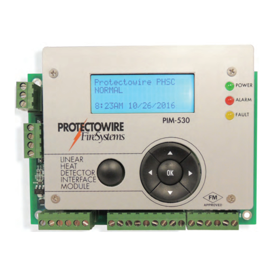
Page 7: The Pim-530 Interface Module
Interface Module General Information The Protectowire PIM-530 is a detection control module that is an interface between a main fire alarm control panel detection circuit or addressable node and Protectowire Digital Linear Heat Detector. The module provides one (1) supervised detection circuit that may be field wired for either Class A (Style D) or Class B (Style B) service. -
Page 8: Specifications
• Power Limited, onboard surge and EMI protection devices Inputs • One initiating device circuit capable of monitoring up to 6,560 feet (2,000m) of Protectowire PHSC and PLR Digital Linear Heat Detectors • For intrinsically safe applications (Option I), the maximum detector length per zone is 6,560 feet... -
Page 9: 4-20Ma Output Information
4-20mA Output Information Description - The PIM-530 provides two 4-20mA outputs that allow for monitoring of the module status and active alarm point location reading. These outputs are intended for annunciation purposes only. Module monitoring is intended to be accomplished using the on board supplied dry contacts connected to a listed or approved fire detection control panel initiating device circuit. -
Page 10: Installation And Wiring
GND terminal and COM terminal must be connected to each other. EARTH GND POWER POWER STATUS 12-24VDC INDICATORS ALARM 1.6 WATT FAULT PROTECTOWIRE LINEAR END LINE ZONE HEAT DETECTOR (CLASS B) END LINE RESISTOR WATT FEED CABLE NAVIGATION SWITCHES... -
Page 11: Detector Wiring
6,560 feet (2,000m) of Protectowire Digital Linear Heat Detector. The PIM-530 initiating circuit is designed to monitor Protectowire Digital Heat Detector and also supports other types of normally open contact alarm initiating devices. Two wire smoke detectors which require initiating device circuit power to operate are not supported. -
Page 12: 4-20Ma Outputs Wiring
Installation and Wiring – (continued) 4-20mA Output Wiring – The PIM-530 provides two 4-20mA outputs which allow the status of the module to be remotely monitored. See the specifications section of this manual and the 4-20mA Output Information section for additional information on each outputs function. Step 1 –... -
Page 13: Configuration & Feature Selection
5 3 0 T E R F A Configuration and Feature Selection g i f o i t Feat Configuration Prerequisites - The PIM-530 must be configured and tested before service. Configuration and testing of detection equipment shall be performed by competent, qualified personnel having jurisdiction must configured tested... -
Page 14: Resetting The Detector
5 3 0 T E R F A Password Entry Screen Password Error Screen tion buttons buttons down tion tion buttons Use the left and right navigation buttons to select each character and the up and down navigation buttons to change character. -
Page 15: Detector Type Selection
PHSC (Protectowire Heat Sensitive Cable) and then return the user to is currently configured for PHSC (Protectowire Heat Sensitive Cable) and then return the user to the main menu. is currently configured for PHSC (Protectowire Heat Sensitive Cable) and then return the user to the main menu. -
Page 16: Display Units
Display Units – The PIM-530 can be configured to display measurement information in either Standard figur disp (Temperature = ˚F, Distance = Feet) or Metric units (Temperature = ˚C, Distance = Meters). Select a unit type d (Tem (Tem ˚ Feet) (Tem (Tem... - Page 17 Figure 4 Before beginning the calibration procedure place a short across the beginning (ZERO distance) of the Before beginning the calibration procedure place a short across the beginning (ZERO distance) of the Before beginning the calibration procedure place a short across the beginning (ZERO distance) of the Before beginning the calibration procedure place a short across the beginning (ZERO distance) of the Before beginning the calibration procedure place a short across the beginning (ZERO distance) of the Before beginning the calibration procedure place a short across the beginning (ZERO distance) of the...
- Page 18 Press the OK button to begin the ZERO distance calibration. The module will measure the resistance to the utto b i l o ti s i s beginning of the detector run and offset future readings by this value. etecto ffset futur >...
- Page 19 “O K” utto P:” display d. Se c le “2: CAL END P T./SP T./SP nu and pr “OK” but T./SP nu and pr “OK” but “OK” but on. The O CAL END Dis ill be display ill be display utto b i l o ti...
-
Page 20: Time And Date Setup
T H E C T M 5 3 0 R F A C E Time and Date Setup – The PIM-530 features a real time clock with date. Time is displayed in 12 hour for- – l ea time l ea time Time display... -
Page 21: Event History
te n affected. d Da – d Da te n te n affected. t e s sswo – t e s – le c To perform a factory restore enter the setup menu and select the “10: FACTORY RESTORE” menu item and press the “OK”... -
Page 22: 4-20Ma Outputs Calibration
Once even been selected using the navigation navigation UP/Down press “OK” button view navigation UP/Down press “OK” button view view additional selected event. show shown screen shots below, event condition shown screen shots below, event condition channel is selected > >... -
Page 23: Testing Notes
Class A (Style D) or Class B (Style B) service. This initiating device circuit is capable of operating up to 6560 feet (2000 meters) of Protectowire Digital Linear Heat Detector or equivalent combi- nation of detector and feed cable. See Figure 8 for an example of a typical field wiring for Class A and B con- figuration. -
Page 24: Test Open Circuit Monitoring
Figure 12 Figure 12 Step 1 – Test Open Circuit Monitoring- At the end of the Protectowire Linear Heat Detector, open the Figure 8 circuit by disconnecting one leg of the detector from the ELR, see Figure 13, or return field terminals, see Figure 14. -
Page 25: Test Alarm Monitoring
NORMAL” standby condition. NORMAL” standby condition. Open Fault Display Normal Standby Display connect jumper Step 2 – Test Alarm Monitoring – At the end of the Protectowire Linear Heat Detector, connect a jumper – – Protectowire – Protectowire Protectowire... - Page 26 5 3 0 T E R F A After approximately seconds display should display ” long with Figure 12 distance alarm point ACTIVE m ” should alternate every seconds between a ” – After approximately 10 seconds the PIM-530 LCD display should display an “ALARM” message along with a information being measured direction.
-
Page 27: Intrinsic Safety Barrier, Option I
9/7/16 DESCRIPTION: Some applications of PROTECTOWIRE PIM-530 linear heat detection circuits require energy limiting to prevent explosions in areas classified as hazardous locations. One method used to accomplish this “Intrinsic Safety” is to utilize diode shunt barriers. Diode shunt barriers consist of zener diodes with current limiting resistors which “shunt” excess voltage spikes to ground. -
Page 28: Isb Illustration Drawing Il-1626D
87 mH 87 mH APPLICATION AS DETAILED HE La � (( 2.5 uH / ft. ) x ( PROTECTOWIRE ft. )) + (Lfc) Ca � (( 35 pF / ft. ) x ( PROTECTOWIRE ft. )) + (Cfc) < MOUNTING TRACK 6. -
Page 29: Modbus Over Rs-485 Operation Guide Descriptions
Modbus Over RS-485 Operation Guide RS-485 Description RS-485 is a standard which describes a physical layer utilized in serial communication. RS-485 allows for installation of inexpensive local network systems and supports multi-drop communication links. Due to its use of differential balanced line signaling over twisted pair wiring, RS-485 can span distances of up to 4,000 feet (1,220 meters) without repeaters. -
Page 30: Specifications
Specifications Port Specifications • RS-485 Serial Port compatible with TIA/EIA-485-A specifications • Supports Half Duplex Mode (2 Wire) • Baud Rates Supported, 9.6K, 19.2K, 57.6K, 115.2K • Bus Load, 1/8th Load • Biasing, None • Wiring method, Two wire with common via module power supply common. Protocol Information •... -
Page 31: Wiring
Wiring Wiring connections for the RS-485 port are made via Terminal J12 on the lower right corner of the module. Wiring should be made using communications cable suitable for the environment and rated for the intended purpose. Each module requires three connections to the communication bus. Transmit +, Transmit – and common. The module operates in half duplex mode. -
Page 32: Configuration Settings
Configuration Settings Once properly wired to the communication bus each module must be configured to communicate on the net- work. The following network settings must be known before configuring the module. ion bu h modu ommu Slave Address e fo etwo gs must b gs must b... -
Page 33: Setting The Slave Address
Use the down navigation key to scroll to the “MODBUS” menu item and then press the center button to “M ODBU S” e it enter the Modbus menu. > > ress – “ MODB US” /DOWN Setting the Slave Address –... -
Page 34: Setting The Baud Rate
Setting the Baud Rate – Once in the “MODBUS” menu use the UP/DOWN navigation keys to select Baud – “ MODB US” /DOWN the “BAUD RATE” menu item. “BA ” i t a e l e re i d rat . -
Page 35: Module Status
Module Status – The PIM-530 Status is available from a single 16 bit Modbus holding register at protocol address 40001. Each bit of the holding register represents a function status of the module. The status bits are Module Status – The CTM-530 Status is available from a single 16 bit Modbus holding register at arranged so monitoring only the 3 least significant bits provides the priority status of the module. -
Page 36: Event Distance Measurements
Event Distance Measurements – The M-530 event distance measur ments are available as a single integer value at Modbus holding register 40006 through 40009. These values are only available when Alarm status has been detected on the corresponding out or return terminals. The distances are available in both Feet and Meters. - Page 37 The Protectowire Company, Inc. 60 Washington Street, Pembroke, MA 02359 U.S.A. p:781-826-3878 f:781-826-2045 web: www.protectowire.com email: pwire@protectowire.com MAN2007D-0420 SPECIAL HAZARD FIRE DETECTION SYSTEMS...
Need help?
Do you have a question about the PIM-530 Series and is the answer not in the manual?
Questions and answers