
Related Manuals for Quanser QNET

Summary of Contents for Quanser QNET
- Page 1 USER MANUAL QNET Myoelectric Trainer for NI ELVIS Set Up and Configuration CApTIVATE. MoTIVATE. GRAdUATE.
- Page 2 Fax: 1-905-940-3576 Printed in Markham, Ontario. For more information on the solutions Quanser Inc. offers, please visit the web site at: http://www.quanser.com This document and the software described in it are provided subject to a license agreement. Neither the software nor this document may be used or copied except as specified under the terms of that license agreement.
-
Page 3: Table Of Contents
Contents Introduction System Description MYOELECTRIC Components System Schematic Specifications Environmental Setup Guide QNET and NI ELVIS II Setup QNET LabVIEW Hints Scaling Scopes Saving Response Troubleshooting General Software Issues General Hardware Issues Technical Support v 1.0 QNET MYOELECTRIC- User Manual... -
Page 4: Introduction
Section 2. A schematic of the hardware components is included in Section 3, and the specifications are listed in Section 4 and Section 5. Some helpful LabVIEW hints when using the QNET VIs are given in Section 7 along with a troubleshooting guide in Section 8. -
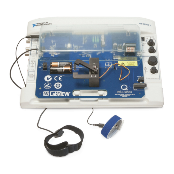
Page 5: System Description
The components comprising the Myoelectric Trainer are labeled in Figure 2.2, and are described in Table 1. Caution: Ensure the trainer is setup as dictated in the QNET Setup Guide. The trainer is susceptible to protection impairment if not used as specified. - Page 6 Caution: Please make sure you use the correct type of wall transformer or you will damage the system. It should supply 15 VDC and be rated at 5.0 A. The QNET Myolectric does NOT use the same power supply as other QNET systems.
-
Page 7: System Schematic
A schematic of the MYOELECTRIC system interfaced with a DAQ device is provided in Figure 3.3. The block diagram representing the circuit in the Myoelectric board is shown in Figure 3.4. Figure 3.3: Schematic of QNET Myoelectric trainer Figure 3.4: QNET Myolectric circuit block diagram v 1.0... -
Page 8: Specifications
Supply voltage (typical) 5.00 Isolation Amplifier: ±0.200 Recommended input voltage (accurate and linear) M AX Maximum differential input voltage 0.308 M AX Gain Output low voltage 1.29 Output high voltage Bandwidth Supply Voltage Table 2: MYOELECTRIC specifications QNET MYOELECTRIC- User Manual... -
Page 9: Environmental
Table 3: MYOELECTRIC environmental operating conditions Caution: Ensure the unit is operated under the temperature and humidity conditions given in Table 3. Otherwise, there may be some issues with the heating and cooling results. v 1.0 QNET MYOELECTRIC- User Manual... -
Page 10: Setup Guide
6 SETUP GUIDE As illustrated in Figure 6.5, the QNET boards can easily be connected to an NI ELVIS system. The instructions in Section 6.1 detail the setup procedure for using a QNET with an NI ELVIS II. Figure 6.5: Connecting a QNET Trainer Caution: Do not position the ELVIS II so that it is difficult to disconnect the main power. -
Page 11: Qnet And Ni Elvis Ii Setup
6.1 QNET AND NI ELVIS II SETUP The procedure to install a Quanser Engineering Trainer (QNET) module on the NI ELVIS II is detailed in this section. The NI ELVIS II components used in the installation procedure are located and marked by an ID number in Figure 6.6, and described in Table 4. - Page 12 1. Place the small opening on the front of the QNET board over the mounting bracket on the NI ELVIS II. 2. Slide the PCI connector of the QNET module end into the female connector on the NI ELVIS II. Make sure it is connected properly.
- Page 13 Figure 6.8: QNET LEDs should all be ON 11. Power ON the myoelectric sensor power. 12. Ensure that the Battery ON LED is lit, as shown in Figure 6.9. Figure 6.9: Battery LED should be ON v 1.0 QNET MYOELECTRIC- User Manual...
-
Page 14: Qnet Labview Hints
7 QNET LABVIEW HINTS 7.1 SCALING SCOPES This section describes a handy method of changing the x or y axis in a LabVIEW scope using QNET_DCMCT_Swing_Up_Control VI as an example. Read the steps below to reduce the y-axis range of the Angle (deg) scope shown in Figure 7.10 in order to see the blue trace more up close. -
Page 15: Saving Response
2. Apply the same scale change to both the output and input scopes. Otherwise, the data plotted in each scope will not be synchronized with each other. 7.2 SAVING RESPONSE Read the following to save a scope response: 1. Right-click on the scope and select Export Simplified Image, as shown in Figure 7.13 v 1.0 QNET MYOELECTRIC- User Manual... - Page 16 2. The dialog box shown in Figure 7.14 opens and gives various image export options. One way is to export the image to the clipboard as a bitmap. This can then be pasted in a graphical software (e.g MS Paint, Irfanview) and saved to a desired format (e.g. gif). Figure 7.14: Export Simplified Image dialog box QNET MYOELECTRIC- User Manual...
- Page 17 The scope can be saved whether or not the VI is running. However, typically it is easier to stop the VI when the desired response is collected and then export the image as instructed above. v 1.0 QNET MYOELECTRIC- User Manual...
-
Page 18: Troubleshooting
8 TROUBLESHOOTING 8.1 GENERAL SOFTWARE ISSUES Q1 When I try to open a QNET VI, it says there are some missing VIs and they have a ''CD'' or ''Sim'' in the name? The LabVIEW Control Design and Simulation Toolkit is not installed. - Page 19 1. Go through the ELVIS II setup procedure outlined in the QNET Setup Guide 2. Once completed, launch the Measurement & Automation Explorer software. 3. As illustrated in Figure 8.16, expand the Devices and Interfaces and NI-DAQmx Devices items and select the NI ELVIS II device.
-
Page 20: Technical Support
9 TECHNICAL SUPPORT http://www.quanser.com/ To obtain support from Quanser, go to and click on the Tech Support link. Fill in the form with all the requested software and hardware information as well as a description of the problem encountered. Also, make sure your e-mail address and telephone number are included. - Page 21 (EMG) Quanser QNET add-on boards for the NI ELVIS platform teach introductory control topics in undergraduate labs cost-effectively. All QNETs are offered with comprehensive, ABET*-aligned courseware that have been developed to enhance the student learning experience.
Need help?
Do you have a question about the QNET and is the answer not in the manual?
Questions and answers