Advertisement
- 1 Introduction
- 2 Description of tools and symbols
- 3 Controller Features
- 4 Controller Illustration
- 5 Wiring Sequences
- 6 LCD Display Illustration
- 7 Button Setting Info
- 8 Battery Type & Parameter Settings
- 9 Controller Error List & Recovery
- 10 Controller Specifications
- 11 Product Dimension
- 12 Documents / Resources
Introduction
This device is a PWM 12/24V 20A solar battery charge controller ideal for many applications. Its flush mount design makes it a perfect solution for RV's, boats and remote power applications. Please be sure to read this manual to familiarize yourself with the features and operation of the controller.
Description of tools and symbols
| Marks & | Item | Description |

|
High Voltage Danger Mark | High voltage might exist inside the controller. Service only by professional. |

|
Heating Caution | Controller surfaces may be hot in operation. |

|
EU WEEE Mark | Do not dispose as trash. |

|
Wire Stripper | For wire stripping. |

|
Volt Meter | To check the positive/negative connection, and to check current or other electrical value. |

|
Anti-static Glove | To avoid controller damage caused by static electricity from human body. |

|
Electric Tape | To tape the wiring joint for safety. |

|
Screwdriver | To mount the controller. |
Controller Features
The PWM solar charge controller is used for solar charging of batteries from a 12V or 24V solar panel. It features a low voltage disconnect control on the load output to prevent battery damage. It has an LCD screen to display solar, battery and load voltages and currents.
- User-friendly key press operation; simpler and easier.
- 5V USB power port for charging mobile devices.
- Multiple load output control mode selections: light control, light + time, test & debug, manual and always-on modes are supported.
- Industrial grade design for operation in harsh environments.
- Full range of electrical protections; Solar & battery disconnect protection, battery over-discharge, system over-voltage, etc.
- All common battery types are supported: AGM, GEL, Flooded Lead Acid and Li-Ion.
- 12/24V Battery Voltage Auto Select for all lead acid types of battery.
- PWM 3 Phase Charging – Equalize, Boost, Float.
- Supports 20A on solar input and 20A on load output.
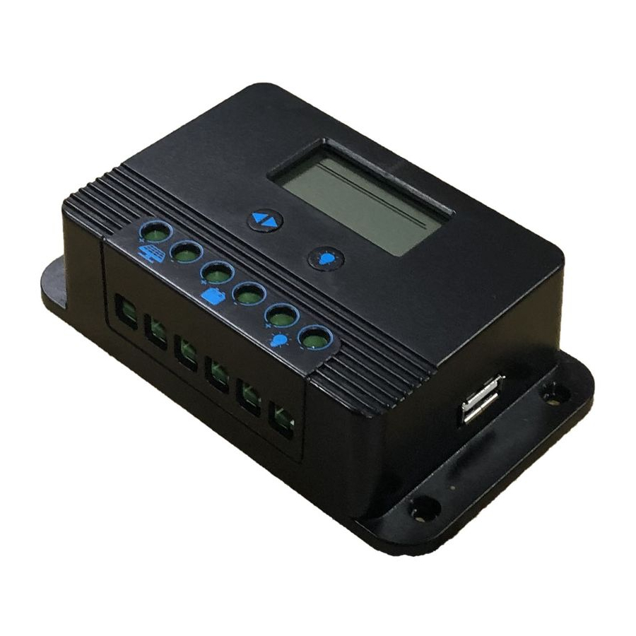
Controller Illustration

| 1 | LCD Display | 5 | Load wiring terminal |
| 2 | Menu Key | 6 | Function Key |
| 3 | Solar input wiring terminal | 7 | USB Port |
| 4 | Battery wiring terminal | 8 | Installation holes |
Wiring Sequences

- First: Connect the battery first, please choose cable size accordingly.
- Second: Connect the solar panel
- Last: Connect the load wiring to the load (if necessary)
LCD Display Illustration

- Display Section
| ITEM | ICON | |
| Status | Current system working status |

|
| Parameter | Parameter value for selected item |

|
| Selected Item | Current selected item |
- Solar (PV), Battery & Charge Indications
![]()

- Operations

Remarks:
*The page will enter to the next one if no operation in 3 seconds
*The system will automatically enter to the "error"page when there is an error detected. This page will stay still until the user operates in the controller to enter to the other pages.

Button Setting Info
| BUTTON | SETTING STATUS | PRESS | FUNCTION |
 |
In Setting | Long press | Enter page not for settings |
| Short press | Enter next page not for settings | ||
| Not in Setting | Long press | Enter page not for settings | |
| Short press | Enter next page not for settings | ||
 |
In Setting | Long press | No function |
| Short press | To adjust parameter | ||
| Not in Setting | Short press | Load switch (in manual mode) |
Remark: "In Setting" means the user is in the page for setting parameters.
Battery Type & Parameter Settings
- Battery Type Setting

ITEM BATTERY TYPE DESCRIPTION FLD Flooded battery Battery system voltage auto recognition; parameters default set. SEL Sealed/AGM battery GEL Gel battery LI Lithium battery System voltage, charge/discharge parameters adjustable

- System Voltage(For Li battery only)

- Charge Voltage Settings (For Li battery only)
![]()
- Over-discharge Voltage Settings (For Li battery only)
![]()
- Load ModeSettings
![]()


| MODE NUMBER | DEFINITION | DESCRIPTION |
| 0 | Light switch control | The PV voltage turns on the load switch in time of light control delay |
| 1~14 | Light + Time control | The PV voltage turns on the load switch and shut it down in time of settings |
| 15 | Manual switch | Turns on/off the load by press the load button |
| 16 | Testing switch | Turns on the load immediately with no delay and then turns off |
| 17 | Always on | The load keeps on until battery low voltage disconnect |
Controller Error List & Recovery
| CODE | DRROR | ANALYSIS | RECOVER SOLUTION |
| E00 | No error | -- | -- |
| E01 | Over-discharged | The battery voltage has been discharged to a low level, load cuts off | Recover once the battery voltage return to the normal level. Load is allowed to turn on then. |
| E02 | Battery over voltage | The battery voltage has exceeded the max level. | Recover once the battery voltage return to normal level. |
| E04 | Load short circuit | The load gets short circuited | Check the wiring and loading condition. |
| E05 | Load over loaded | The load power has exceeded the rated value | Check and decrease the load power requirement. |
| E06 | Device over heating | The controller gets too hot in high temperature, the charge cuts off | Get the device cooler to decrease the temperature |
| E08 | Charge power over rated | The input power has exceeded the max rated value | To decrease the input power |
| E10 | PV over voltage | The PV input voltage is too high | To decrease the input voltage |
| E13 | PV anti- connection | The PV side has anti-connection | Check and re-connect the PV wires in right position |
| E14 | Battery anti-connection | The battery side has anti-connection | Check and re-connect the Battery wires in right position |
Controller Specifications
* Remark "n": when system voltage is 12V, n=1; when system voltage is 24V, n=2
| ITEM | PARAMETERS | |||
| Model No. | TP-SC24-20 | |||
| System Voltage | 12V/24VAuto(FLD/GEL/SLD), 12V/24V(manual set for Li) | |||
| No-load Loss | 8ma(12V),12ma(24V) | |||
| Max PV Input Voltage | < 55V | |||
| Rated Charge Current | 20A | |||
| Max PV Input Power | 340W/12V;680W/24V | |||
| Battery Type Selection | FLD | SEL | GEL | LI |
| Equalize Charge Voltage | 14.8V*n | 14.6V*n | -- | -- |
| Boost Charge Voltage | 14.6V*n | 14.4V*n | 14.2V*n | 14.4V*n (adjustable) |
| Float Charge Voltage | 13.8V*n | -- | ||
| Boost Charge Recovery Volt | 13.2V*n | -- | ||
| Over Discharge Recovery Voltage | 12.6V*n |
12.6V*n (auto adjust to the over discharge voltage) |
||
| Over Discharge Voltage | 11.1V*n | 11.1V*n(adjustable) | ||
| Light Control Voltage | 5V(12Vsystem),10V(24Vsystem) | |||
| Light Control Delay Time | 10s | |||
| Load Modes | light control(dusk-to-dawn), light + time control, debug mode, manual control, steady-on mode. | |||
| Operation Temperature | -25℃ ~ +65℃ | |||
| IP Protection | IP30 | |||
| Net Weight | 200g | |||
| Display | LCD | |||
| Operation Altitude | ≤ 3000M | |||
| Controller Size | 122*70*34.5mm | |||
Product Dimension

Documents / ResourcesDownload manual
Here you can download full pdf version of manual, it may contain additional safety instructions, warranty information, FCC rules, etc.
Advertisement


Need help?
Do you have a question about the TP-SC24-20 and is the answer not in the manual?
Questions and answers