
Subscribe to Our Youtube Channel
Related Manuals for ATAGO CM-800A-DMF


Summary of Contents for ATAGO CM-800A-DMF
- Page 1 3534-E06 In-line Dimethylformamide Monitor CM-800 -DMF Instruction Manual Cat.No.3534...
-
Page 3: Table Of Contents
15. Setting the Recorder Output ..........................30 16. Cleaning the Prism..............................32 17. Error Codes & Troubleshooting..........................33 18. Consumable Parts and Optional Items ......................34 (1) Consumable Parts............................34 (2) Optional Items ..............................34 19. Specifications................................35 20. Dimensions.................................36 21. Repair Service and Warranty Period ........................37 22. ATAGO CO.,LTD. Service Centers........................38... -
Page 4: Precautions For Use
1. Precautions for Use Introduction Thank you for purchasing the instrument. Before using the instrument, read this instruction manual carefully, and keep it on hand for future reference. For safe use --- Be sure to observe the following. To prevent injury and damage to property, safely operate the instrument by observing the precautions outlined in this manual. - Page 5 If the AC adapter AD-32, AD-33 or AD-34 (optional) is used, remove the power cable plug from the AC 100-240V outlet. Fire or malfunction may result if the instrument continues to be used. Contact your ATAGO Distributor for an inspection. ...
- Page 6 Handling of this instrument (Continued) CAUTION ◇ DO NOT measure any sample that can ◇ If the sample could possibly stain the prism, damage the prism or the sample inlet unit. immediately clean the prism according to the ◇ Sample temperature should be kept between procedure described on page 32 5℃...
- Page 7 ◇ The AC adapter AD-32 (AD-33 or AD-34) For repair service of the power cable and plug must be inserted into an AC 100-240V plug, contact an Authorized ATAGO Service outlet. Other outlets may result in a short Center. circuit, smoke, or fire.
- Page 8 Connection of optional component (printer, etc.) WARNING ◇ Turn off the power (DC24V) prior to connecting cables to the individual units. If the AC adapter AD-32, AD-33 or AD-34 (optional) is used, pull out the power cable plug from the AC100-240V outlet before connecting.
- Page 9 Conditions to be observed when using Environmental conditions ◇ Use the instrument at an altitude below 2,000m (above sea level). ◇ Use the instrument indoors. ◇ Use the instrument where the temperature is between 5 to 40℃. ◇ Do not leave the instrument in a location exposed to direct sunlight or near a heating unit where the temperature may rise.
-
Page 10: Refractive Index And Dimethylformamide(Dmf) Concentration
2. Refractive Index and Dimethylformamide (DMF) concentration The instrument is a refractometer that detects the Refractive Index of a sample and outputs the DMF concentration(%) value on the display. (1) What is refractometer? When a straw is placed into a glass filled with water, the straw appears to bend. When a straw is placed into a glass filled with sugar water, the straw appears to bend much more sharply than in the case of water alone. -
Page 11: Unpacking And Installation
① Main unit and standard accessories. ② through ⑥ are optional items and are included with the main unit if ordered. Additional items can be ordered at any time. For details, please contact an Authorized ATAGO Distributor. ① In-line Salinity Monitor CM-800α-DMF (Cat.No.3534) •... -
Page 12: Unpacking
(2) Unpacking ① Unpack the instrument and confirm that there is no external damage. ② Confirm that all parts of the main unit, accessories, and any optional units as described in section "(1)Configuration" (C page 9) are included. (3) Installation ... -
Page 13: Names And Functions Of Components
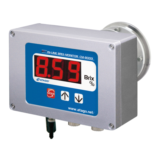
4. Names and Functions of Components (1) Instrument ③ ① Prism Corrosion resistant optical glass, with a polished surface to reflect light. ② Prism stage ④ Connected to the sample inlet and fastened by ④ a clamp band. ③ Radiator Disperses heat when measuring high temperature samples to prevent the electric ①... -
Page 14: Operation Display
(2) Operation Display ① Measurement value display Digitally displays the measurement value [DMF(%)], setting mode, and other setting 12.3 ① values. ② Switches or sets the display mode of the measurement value and the setting mode. Setting mode Setting description number ②... -
Page 15: Mounting The Instrument And Ac Adapter Ad-32 (Ad-33 Or Ad-34) (Optional)
5. Mounting the instrument and AC adapter AD-32 (AD-33 or AD-34) (Optional) ◇ Turn off the power (DC24V) before mounting. If AD-32 (AD-33 or AD-34) is used, disconnect the power cable's plug from the AC 100-240V outlet before beginning. WARNING Electrical shock may occur if the unit is mounted with the power connected. -
Page 16: Mounting The Sample Inlet Unit
6. Mounting the Sample Inlet Unit ◇ Turn off the power (DC24V) before mounting. If AD-32 (AD-33 or AD-34) is used, disconnect the power cable's plug from the AC WARNING 100-240V outlet before beginning. Electrical shock may occur if the unit is mounted with the power connected. - Page 17 Mounting procedure ① Install the instrument so that the prism Prism stage surface is at a right angle to the ground. O-ring ② Attach the sample inlet unit to the instrument (silicon or EPDM) with O-ring (accessory) inserted between them, and fasten them together with the clamp band (accessory).
-
Page 18: Installation Of The Instrument Without The Sample Inlet Unit (Optional)
The tie bands are made of plastic. If measuring chemicals that are corrosive to plastic, use tie bands made of an alternative material. N Tie bands can be ordered through your ATAGO Distributor. Fig. 6-7 C "18.Consumable Parts and Optional Items"... -
Page 19: Connecting The Power Cable Or Ac Adapter Ad-32 (Ad-33 Or Ad-34) (Optional)
7. Connecting the Power Cable or AC Adapter AD-32 (AD-33 or AD-34) (Optional) ◇ Turn off the power (DC24V) when connecting or disconnecting the power cable (for DC24V) or the DC output cable of the AD-32 (AD-33 WARNING or AD-34) to or from the terminal. When AD-32 (AD-33 or AD-34) is used, remove the power cable plug from the AC 100-240V outlet. -
Page 20: When The Ac Adapter Ad-32, Ad-33 Or Ad-34 (Optional) Is Used
(2) When the AC adapter AD-32, AD-33 or AD-34 (Optional) is used Attach the connector of the DC output cable of the AD-32 (AD-33 or AD-34) to the power (DC24V) input terminal at the bottom of the instrument. Connect the opening of the input terminal with the connector pin and insert the connector. Then turn the connector ring clockwise to fasten the connector. -
Page 21: External Output
8. External Output ◇ When connecting or disconnecting the Recorder Output Cable or RS-232C Cable to the instrument, be sure to turn off the power WARNING (DC24V). If AD-32 (AD-33 or AD-34) is used, be sure to remove the plug from the outlet before connecting these cables. -
Page 22: Rs-232C Output
(2) RS-232C output The instrument features a RS-232C output for computers. The RS-232C cable is an optional accessory. When using the RS-232C cable, the instrument and the PC should be separated by no more than 15 meters. ① RS-232C output cable and code tables (Fig. 8-2) 1 to 15m Clamp filter Approx. - Page 23 ② Preparing a PC for Data Transmission Download a terminal emulator for PC serial communication. Here, the open-source software “Tera Tarm” is used as an example. Download Tera Term from a website, such as the one below: http://ttssh2.sourceforge.jp/index.html.en/ (1) Start Tera Term. Select "serial"...
- Page 24 (3) The serial settings are conformed to the instrument settings. Enter the port number selected in step (1). Click OK. (4) Click Setup, and then Terminal port. (5) Enter the settings as shown below and Click OK. ※ Make sure that the "Local echo" is checked.
- Page 25 ③ Transmit data Every time a measurement is taken, a new row of data appears in the Tera Term window. Fixed range (No zero suppression) : ○○.○○,△△△.△ CR / LF ○○.○○ : DMF(%) The DMF(%) display range is "-2.00 to 40.50". Example Display DMF(%)
-
Page 26: Power Supply
AC 100-240V. ◇ NEVER use a power cable that is damaged, cut, broken, or altered. Fire, electrical shock or burns may occur. To purchase replacement power cables, contact an Authorized ATAGO Distributor. ◇ NEVER plug the AD-32 (AD-33 or AD-34) AC Adapter in with wet hands. -
Page 27: Measuring Dmf Solution(%)
If this happens, please discontinue use of the instrument and contact an Authorized ATAGO Distributor to assist with inspection and/or repair. Continued use may cause fire or a malfunction of the unit. ◇ NEVER repair, modify, or disassemble the instrument. Fire, electrical shock or burns may occur. -
Page 28: Setting The Temperature Scale (℃/°F)
11. Setting the temperature scale (℃/°F) ① Turn on the power (24V DC) according to the instructions on page 24, "9.Power Supply" The unit will display the real-time measurements in DMF(%). ② Hold down the key for one second. Once [t] appears, press the key. -
Page 29: Setting The Measurement Interval And Mode-S Level
12. Setting the Measurement Interval and Mode-S Level The Mode-S feature is designed to improve the measurement stability of samples that may have conventionally resulted in fluctuating readings. ① Turn on the power (24V DC) according to the instructions on page 24, "9.Power Supply" The unit will display the real-time measurements in DMF(%). -
Page 30: Adjusting To The Reference
13. Adjusting to the Reference m Before adjusting to a reference solution, confirm that the prism surface is clean. ① Confirm that the sample inlet unit is properly connected to the piping. ② Let tap water or a reference sample flow through the piping. -
Page 31: Temperature Correction
14. Temperature Correction ● About temperature correction The Refractive Index of every substance varies with the temperature. When measuring the Refractive Index of a liquid with a refractometer, the measurement value will also vary according to the sample temperature. ● About temperature correction for the instrument The instrument is programmed with a temperature coefficient that is specific to DMF concentration within the measurement temperature range of 5 to 40 ℃. -
Page 32: Setting The Recorder Output
15. Setting the Recorder Output The instrument can output a DC 4 to 20mA signal across a specified range of DMF(%). The upper and lower limit values can be set. The lower limit value of DMF(%) should be set in the range of -2.0 to 39.5%. The upper limit value of DMF(%) should be set in the range of -1.0 to 40.5%. - Page 33 ⑦ Press the key again and the display turns to [4] (Fig. 15-3). ⑧ Press the key. The current upper limit value will blink on the display (Fig. 15-4). ⑨ Adjust the displayed value to the desired upper limit value by using the and/or keys.
-
Page 34: Cleaning The Prism
16. Cleaning the Prism ◇ Before running hazardous substance(s) through any system, necessary precautions should be taken to ensure the safe handling of the WARNING hazardous substance(s). If using a sample inlet unit, use caution when disconnecting the instrument unit. ... -
Page 35: Error Codes & Troubleshooting
32. If [EE.E] is continually displayed after the above procedures have been carried out, please contact an Authorized ATAGO Distributor. Blinking The prism temperature is Run a sample at a temperature of 5 to 40℃. -
Page 36: Consumable Parts And Optional Items
O-ring (Viton) RE-68002 (2) Optional Items The following optional items are available for the instrument. These items can be ordered through an Authorized ATAGO Distributor. C "3.Unpacking and Installation" page 9 Catalog or Product or part name Description... -
Page 37: Specifications
Temperature Based on the temperature correction table for Dimethylformamide. correction values The values obtained at the ATAGO laboratories are used. Output ① Recorder output: DC 4 to 20mA (Optional Cables) Dimethylformamide concentration up to 40.5% can be set in 1% increments. -
Page 38: Dimensions
20. Dimensions Instrument (weight: 2.4kg) Front (display unit) Side Back (detecting unit) AD-32 / AD-33 / AD-34 Back Side Front... -
Page 39: Repair Service And Warranty Period
The instrument is a precise electronic instrument which incorporates both optical and electrical components. Due to the complex interaction of these components, repairs and/or adjustments of the instrument unit must be performed by an ATAGO engineer or a properly trained service technician at an ATAGO Authorized Service Center. Authorized Service Center technicians have completed maintenance courses and have a vast knowledge of ATAGO instruments. -
Page 40: Atago Co.,Ltd. Service Centers
22. ATAGO CO.,LTD. Service Centers ATAGO has Authorized Service Centers around the world. Below is the list of countries where you can find an ATAGO Authorized Service Center. If your ATAGO instrument requires servicing please contact ATAGO at the following e-mail address. - Page 42 Headquarters: The Front Tower Shiba Koen, 23rd Floor 2-6-3 Shiba-koen, Minato-ku, Tokyo 105-0011, Japan TEL: 81-3-3431-1943 FAX: 81-3-3431-1945 overseas@atago.net http://www.atago.net/ 11811 NE First Street, Suite 101, Bellevue, WA 98005 U.S.A. TEL: 1-425-637-2107 FAX: 1-425-637-2110 customerservice@atago-usa.com TEL: 91-22-28544915 / 40713232 customerservice@atago-india.com TEL: 66-21948727-9 ,66-21171549 customerservice@atago-thailand.com...
Need help?
Do you have a question about the CM-800A-DMF and is the answer not in the manual?
Questions and answers