
Related Manuals for ATAGO CM-BASEa(A)


Summary of Contents for ATAGO CM-BASEa(A)
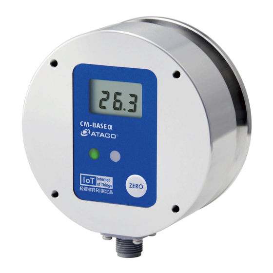
- Page 1 3603-E13 In-line Brix Monitor CM-BASE (A) Cat.No. 3603 CM-BASE (D) Cat.No. 3604 Instruction Manual...
-
Page 2: Table Of Contents
(1) Consumable Parts ............................23 (2) Optional Items ..............................23 15. Relationships between Brix(%) Values and Refractive Index (nD) Values ........ 24 16. Specifications ................................25 17. Repair Service and Warranty Period ......................26 18. ATAGO CO.,LTD. Service Centers ........................27... -
Page 3: Precautions For Use
1. Precautions for Use Introduction Thank you for purchasing the CM-BASEα In-line Refractometer. Before using your CM-BASEα, read this instruction manual carefully, and keep it on hand for future reference. For safe use --- Be sure to observe the following. To prevent injury and damage to property, safely operate the CM-BASEα... - Page 4 Fire or malfunction mask, etc. may result if the instrument continues to be used. Contact your ATAGO Distributor for an inspection. ◇ Do not attempt to repair, modify, or ◇...
- Page 5 Use Short-circuit, smoke, or fire may occur if may result in fire, electrical shock, or other voltages are used. burn. For repair service of the power cable, contact an Authorized ATAGO Service Center. CAUTION ◇...
- Page 6 Conditions to be observed when using Environmental conditions ◇ Use the instrument at an altitude below 5,000m (above sea level). ◇ Use the instrument indoors. ◇ Use the instrument where the temperature is between 5 to 40˚C. ◇ Do not leave the instrument in a location exposed to direct sunlight or near a heating unit where the temperature may rise.
-
Page 7: Refractive Index And Brix
2. Refractive Index and Brix The In-line Refractometer CM-BASEα is a refractometer that detects the Refractive Index of a sample and outputs the Brix(%) value on the display. (1) What is refractometer? When a straw is placed into a glass filled with water, the straw appears to bend. When a straw is placed into a glass filled with sugar water, the straw appears to bend much more sharply than in the case of water alone. -
Page 8: Unpacking And Installation
3. Unpacking and Installation (1) Unpacking ① Unpack the CM-BASEα and confirm that there is no external damage. ② Check that the following items are included. CM-BASEα(A) Cat.No. 3603 Main unit ............. 1 Power and Recorder output cable ....1 ... -
Page 9: Names And Functions Of Components
4. Names and Functions of Components ① Liquid Crystal Display (LCD) ⑥ Connector Displays the measured values. Terminal connect power (DC24V) and output cable. ② ZERO key ⑦ Prism Press to perform zero-setting. Corrosion resistant optical glass, with ③ Indicator Lamp (Green) a polished surface to reflect light. -
Page 10: Mounting The Main Unit To The Bracket Or Stand
5. Mounting the Main Unit to the Bracket or Stand ◇ Turn off the power (DC24V) before mounting. Electrical shock may occur if the unit is mounted with the power WARNING (DC24V) connected. Screw mounting holes (Fig. 5-1) The main unit have four mounting screw holes. Use the mounting screw holes to mount the main unit to the bracket (included), stand Mounting... -
Page 11: Mounting The Sample Inlet Unit
6. Mounting the Sample Inlet Unit ◇ Turn off the power (DC24V) before mounting. Electrical shock may occur if the unit is mounted with the power connected. WARNING ◇ Ensure that the prism is clean and free of any damage and/or scratches. - Page 12 Mounting procedure (Fig. 6-1, Fig. 6-2, and Fig. 6-3) ① Install the CM-BASEα so that the prism surface is at a right angle to the ground. ② Attach the sample inlet unit to the CM-BASEα with O-ring inserted between them, and fasten them together with the clamp band.
-
Page 13: External Output
7. External Output ◇ Turn off the power (DC24V) when connecting the cable from the terminal. WARNING The CM-BASEα(A) transmits data via 4-20mA signals. The CM-BASEα(D) transmits data to a computer via RS-232C. (1) CM-BASEα(A) The provided cable connects to the base of the CM-BASEα(A), and it provides power (DC24V) to the instrument and transmits Brix data via DC 4-20mA. - Page 14 Computer Output ① Computer - Data Setting Download a terminal emulator for PC serial communication. Here, the open-source software “Tera Tarm” is used as an example. Download Tera Term from a website, such as the one below: https://ttssh2.osdn.jp/index.html.en (1) Start Tera Term. Select "serial"...
- Page 15 (3) The serial settings are conformed to the instrument settings. Enter the port number selected in step (1). Click OK. (4) Click Setup, and then Terminal port. (5) Enter the settings as shown below and Click OK.
- Page 16 ② Data Output From Main Unit to PC Every time a measurement is taken, a new row of data appears in the Tera Term window. Fixed range (No zero suppression) : ○○.○,△△.△ CR / LF ○○.○ : Brix(%) The Brix(%) output range is "-2.0 to 33.5". Example Output Data Brix(%)
-
Page 17: Power Supply
Fire, electrical shock or burns may occur. To purchase replacement power cables, contact an Authorized ATAGO Distributor. ① Make sure that the cable is properly connected to the port. ② Once the power (DC24V) is turned on to the instrument, either the green light or red light will come on. -
Page 18: Measuring Brix(%)
9. Measuring Brix(%) ◇ DO NOT measure any sample that can damage the prism or the sample inlet unit. Sample temperature should be kept between CAUTION 10˚C and 50˚C when the power (DC24V) is turned on. ◇ If the sample solution could potentially stain the prism, immediately clean the prism after measurement (following the instructions on page 22 of this instruction manual). -
Page 19: Zero-Setting
10. Zero-setting m Before zero-setting, confirm that the prism surface is clean. ① Confirm that the sample inlet unit is properly connected to the piping. ② Let tap water flow through the piping. ③ Supply power (DC24V) to the CM-BASEα referring to the procedure described in Chapter 7. -
Page 20: Bias Adjustment
11. Bias Adjustment The bias adjustment feature allows the instrument to display readings that have been adjusted by a fixed value added or subtracted from the actual measured value. Hold down the ZERO key for approximately 5 seconds to activate the TEST mode, and the displayed value will start flashing. -
Page 21: Error And Display Lamp
12. Error and Display Lamp (1) During measurement (including when the power is turned on) ●error sign: The red light is on and "LLL" is displayed. <situation> No or an insufficient amount of sample is on the prism surface. solution: Use with a sufficient amount of sample with a Brix of 0.0 to 33.0%. <situation>... -
Page 22: Cleaning The Prism
13. Cleaning the Prism ◇ Before running hazardous substance(s) through any system, necessary precautions should be taken to ensure the safe WARNING handling of the hazardous substance(s). If using a sample inlet unit, use caution when disconnecting the CM-BASEα unit. ◇... -
Page 23: Consumable Parts And Optional Items
RE-68002 Bracket for CM-BASEα RE-67500 (2) Optional Items The following optional items are available for the instrument. These items can be ordered through an Authorized ATAGO Distributor. Part name Part number Description Hose connector Outside diameter of the Hose connector: RE-67501 12mmφ... -
Page 24: Relationships Between Brix(%) Values And Refractive Index (Nd) Values
15. Relationships between Brix(%) Values and Refractive Index (nD) Values The relationships between Brix(%) values and Refractive Index (nD) values are listed in this table for your reference. Relationships between Brix(%) values and Refractive Index (nD) values 1.33299 1.36384 1.39986 1.44193 1.49071 1.33442... -
Page 25: Specifications
16. Specifications ① 3603 CM-BASEα(A) Cat.No ② 3604 CM-BASEα(D) Measurement scale Brix(%) (Automatic Temperature Compensation) Measurement range Brix 0.0 to 33.0% (indication -2.0 to 33.5) Minimum indication Brix 0.1% Brix ±0.5% (for measurement value of Brix 0.0 to Measurement accuracy 33.0%) 10 to 50˚C Measurement temperatures... -
Page 26: Repair Service And Warranty Period
Due to the complex interaction of these components, repairs and/or adjustments of the CM-BASEα unit must be performed by an ATAGO engineer or a properly trained service technician at an ATAGO Authorized Service Center. Authorized Service Center technicians have completed maintenance courses and have a vast knowledge of ATAGO instruments.
Need help?
Do you have a question about the CM-BASEa(A) and is the answer not in the manual?
Questions and answers