Table of Contents
Advertisement
Advertisement
Table of Contents

Related Manuals for ATAGO CM-800OL


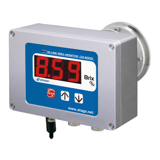
Summary of Contents for ATAGO CM-800OL
- Page 1 3564-E19 IN-LINE BRIX MONITOR CM-800 Cat.No. 3564 Instruction Manual...
-
Page 2: Table Of Contents
19. Consumable Parts and Optional Items .......................38 (1) Consumable Parts............................38 (2) Optional Items ..............................39 20. Relationships between Brix(%) Values and Refractive Index (nD) Values........40 21. Specifications ................................41 22. Dimensions................................43 23. Repair Service and Warranty Period ......................44 24. ATAGO CO.,LTD. Service Centers .......................45... -
Page 3: Precautions For Use
1. Precautions for Use Introduction Thank you for purchasing the In-line Brix-Monitor. Before using the instrument, read this instruction manual carefully, and keep it on hand for future reference. For safe use --- Be sure to observe the following. To prevent injury and damage to property, safely operate the instrument by observing the precautions outlined in this manual. - Page 4 (optional) is used, remove the power cable plug from the AC 100-240V outlet. Fire or malfunction may result if the instrument continues to be used. Contact your ATAGO Distributor for an inspection. ◇ Do not attempt to repair, modify, or ◇...
- Page 5 Handling of this instrument (Continued) CAUTION ◇ DO NOT measure any sample that can ◇ If the sample could possibly stain the damage the prism or the sample inlet unit. prism, immediately clean prism ◇ Cleaning liquids up to 160˚C can be used according to the procedure described on for CIP or SIP.
- Page 6 ◇ The AC adapter AD-32 (AD-33 or AD-34) For repair service of the power cable and plug, contact an Authorized ATAGO plug must be inserted into an AC Service Center. 100-240V outlet. Other outlets may result ◇...
- Page 7 Connection of optional component (printer, etc.) WARNING ◇ Turn off the power (DC24V) prior to connecting cables to the individual units. If the AC adapter AD-32, AD-33 or AD-34 (optional) is used, pull out the power cable plug from the AC100-240V outlet before connecting.
- Page 8 Conditions to be observed when using Environmental conditions ◇ Use the instrument at an altitude below 2,000m (above sea level). ◇ Use the instrument indoors. ◇ Use the instrument where the temperature is between 5 to 40˚C. ◇ Do not leave the instrument in a location exposed to direct sunlight or near a heating unit where the temperature may rise.
-
Page 9: Refractive Index And Brix(%)
2. Refractive Index and Brix(%) The In-line Brix-Monitor is a refractometer that detects the Refractive Index of a sample and outputs the Brix(%) value on the display. The instrument can also transmit measured data to external devices via 4 to 20mA or RS-232C. -
Page 10: Unpacking And Installation
①Main unit and standard accessories. ② through ⑥ are optional items and are included with the main unit if ordered. Additional items can be ordered at any time. For details, please contact an Authorized ATAGO Distributor. ① In-line Brix-Monitor CM-800α (Cat.No.3564) • Main unit •... -
Page 11: Installation
(3) Installation ◇ Before using the recorder output terminal or the RS-232C output terminal, remove the two metallic caps by turning them CAUTION counterclockwise. Fig. 3-1 ① Connect the main unit to an AC100-240V main outlet (voltage fluctuations not to exceed 10%), 50/60Hz with the power cable. -
Page 12: Names And Functions Of Components
4. Names and Functions of Components (1) Main unit of the In-line Monitor ③ ① Prism Sample material contacts the prism surface to allow for the measurement of its Brix(%). ② Prism stage Connected to the sample inlet and fastened ④... -
Page 13: Operation Display
(2) Operation Display ① Measurement value display Digitally displays the measurement value [Brix(%)], setting mode, and other setting ① values. ② Switches or sets the display mode of the measurement value and the setting mode. Setting mode Setting description number Temperature scale ②... -
Page 14: Mounting The Main Unit And Ac Adapter Ad-32 (Ad-33 Or Ad-34) (Optional)
5. Mounting the main unit and AC adapter AD-32 (AD-33 or AD-34) (Optional) ◇ Turn off the power (DC24V) before mounting. If AD-32 (AD-33 or AD-34) is used, disconnect the power cable's plug from the AC 100-240V outlet before beginning. Electrical shock may occur if the unit is mounted with the power WARNING connected. -
Page 15: Mounting The Sample Inlet Unit
6. Mounting the Sample Inlet Unit ◇ Turn off the power (DC24V) before mounting. If AD-32 (AD-33 or AD-34) is used, disconnect the power cable's plug from the AC WARNING 100-240V outlet before beginning. Electrical shock may occur if the unit is mounted with the power connected. - Page 16 Mounting procedure ① Install the main unit so that the prism Prism stage surface is at a right angle to the ground. O-ring ② Attach the sample inlet unit to the main unit (silicon or EPDM) with O-ring (accessory) inserted between them, and fasten them together with the clamp band (accessory).
-
Page 17: Installation Of The Main Unit Without The Sample Inlet Unit (Optional)
The tie bands are made of plastic. If measuring chemicals that are corrosive to plastic, use tie bands made of an alternative material. N Tie bands can be ordered through your ATAGO Distributor. Fig. 6-7 C "19.Consumable Parts and Optional Items" page 38 Fig. 6-8... -
Page 18: Connecting The Power Cable Or Ac Adapter Ad-32 (Ad-33 Or Ad-34) (Optional)
7. Connecting the Power Cable or AC Adapter AD-32 (AD-33 or AD-34) (Optional) ◇ Turn off the power (DC24V) when connecting or disconnecting the power cable (for DC24V) or the DC output cable of the AD-32 WARNING (AD-33 or AD-34) to or from the terminal. When AD-32 (AD-33 or AD-34) is used, remove the power cable plug from the AC 100-240V outlet. -
Page 19: When The Ac Adapter Ad-32, Ad-33 Or Ad-34 (Optional) Is Used
(2) When the AC adapter AD-32, AD-33 or AD-34 (Optional) is used Attach the connector of the DC output cable of the AD-32 (AD-33 or AD-34) to the power (DC24V) input terminal at the bottom of the main unit. Connect the opening of the input terminal with the connector pin and insert the connector. Then turn the connector ring clockwise to fasten the connector. -
Page 20: External Output
8. External Output ◇ When connecting or disconnecting the Recorder Output Cable or RS-232C Cable to the main unit, be sure to turn off the power WARNING (DC24V). If AD-32 (AD-33 or AD-34) is used, be sure to remove the plug from the outlet before connecting these cables. -
Page 21: Rs-232C Output
(2) RS-232C output The instrument features a RS-232C output for computers. The RS-232C cable is an optional accessory. When using the RS-232C cable, the main unit and the PC should be separated by no more than 15 meters. ① RS-232C output cable and code tables Fig. - Page 22 ② Preparing a PC for Data Transmission Download a terminal emulator for PC serial communication. Here, the open-source software “Tera Tarm” is used as an example. Download Tera Term from a website, such as the one below: http://ttssh2.sourceforge.jp/index.html.en/ (1) Start Tera Term. Select "serial"...
- Page 23 (3) The serial settings are conformed to the instrument settings. Enter the port number selected in step (1). Click OK. (4) Click Setup, and then Terminal port. (5) Enter the settings as shown below and Click OK. ※ Make sure that the "Local echo" is checked.
- Page 24 ③ Transmit data Every time a measurement is taken, a new row of data appears in the Tera Term window. Fixed range (No zero suppression) : ○○.○○,△△△.△,☆.☆☆☆☆☆ CR / LF ○○.○○ : Brix(%) The Brix(%) output range is "-2.00 to 80.50". Example Output Data Brix(%)
-
Page 25: Power Supply
◇ NEVER use a power cable that is damaged, cut, broken, or altered. Fire, electrical shock or burns may occur. To purchase replacement power cables, contact an Authorized ATAGO Distributor. ◇ NEVER plug the AD-32 (AD-33 or AD-34) AC Adapter in with wet hands. -
Page 26: Measuring Brix(%)
WARNING supply. If this happens, please discontinue use of the instrument and contact an Authorized ATAGO Distributor to assist with inspection and/or repair. Continued use may cause fire or a malfunction of the unit. ◇ NEVER repair, modify, or disassemble the instrument. Fire, electrical shock or burns may occur. -
Page 27: Setting The Temperature Scale (˚C/˚F)
11. Setting the temperature scale (˚C/˚F) ① Turn on the power (24V DC) according to the instructions on page 24, "9.Power Supply" The unit will display the real-time measurements in Brix(%). ② Hold down the key for one second. Once [t] appears, press the key. -
Page 28: Setting The Measurement Interval And Mode-S Level
12. Setting the Measurement Interval and Mode-S Level The Mode-S feature is designed to improve the measurement stability of samples that may have conventionally resulted in fluctuating readings. ① Turn on the power (24V DC) according to the instructions on page 24, "9.Power Supply"... -
Page 29: Changing The Number Of Decimal Places Displayed
13. Changing the Number of Decimal Places Displayed ① Turn on the power (24V DC) according to the instructions on page 24, "9.Power Supply" The unit will display the real-time measurements in Brix(%). ② Hold down the key for one second, and [t] will appear. Each time the key is pressed, the menu item displayed switches in the order of: [0], [1], [2], [3], [4], and [5]. -
Page 30: Adjusting To The Reference
14. Adjusting to the Reference m Before adjusting to a reference solution, confirm that the prism surface is clean. m Before adjusting to the reference with distilled water, set the temperature correction factor to "1.00". ① Confirm that the sample inlet unit is properly connected to the piping. -
Page 31: Setting The Temperature Correction Values
15. Setting the Temperature Correction Values ● About temperature correction The Refractive Index of every substance varies with the temperature. When measuring the Refractive Index of a liquid with a refractometer, the measurement value will also vary according to the sample temperature. The instrument detects the temperature of the prism, and the Brix(%) indication values are automatically corrected based upon the preset temperature correction values. - Page 32 Table 15-1 Table of temperature correction values for sucrose (g/100g) for refractometer (reference at 20˚C, 589nm) Temp Sucrose (g/100g) eratur (˚C) -0.29 -0.30 -0.32 -0.33 -0.34 -0.35 -0.36 -0.37 -0.37 -0.38 -0.38 -0.38 -0.38 -0.38 -0.38 -0.38 -0.37 -0.37 -0.24 -0.25 -0.26 -0.27 -0.28 -0.28 -0.29 -0.30 -0.30 -0.30 -0.31 -0.31 -0.31 -0.31 -0.31 -0.30 -0.30 -0.30 -0.18 -0.19 -0.20 -0.20 -0.21 -0.21 -0.22 -0.22 -0.23 -0.23 -0.23 -0.23 -0.23 -0.23 -0.23 -0.23 -0.23 -0.22 -0.12 -0.13 -0.13 -0.14 -0.14 -0.14 -0.15 -0.15 -0.15 -0.15 -0.15 -0.15 -0.15 -0.15 -0.15 -0.15 -0.15 -0.15 -0.06 -0.06 -0.07 -0.07 -0.07 -0.07 -0.07 -0.08 -0.08 -0.08 -0.08 -0.08 -0.08 -0.08 -0.08 -0.08 -0.08 -0.07...
- Page 33 ● Inputting the temperature correction factor ① Connect the power according to the procedure described on page 24, section "9.Power Supply". ② The current Brix(%) is displayed on the screen. If there is no sample on the prism surface, [LL.L] will be displayed. ③...
- Page 34 ● Obtaining the temperature correction factor for a sample whose main constituent is other than sugar ① Measure tap water and ensure that the Brix(%) value is 0.0%. If tap water does not read 0.0%, see page 29, section "14.Adjusting to the Reference". ②...
-
Page 35: Setting The Recorder Output
16. Setting the Recorder Output The instrument can output a DC 4 to 20mA signal across a specified range of Brix(%). The upper and lower limit values can be set. The lower limit value of Brix(%) should be set in the range of -2.0 to 79.5%. The upper limit value of Brix(%) should be set in the range of -1.0 to 80.5%. - Page 36 ⑦ Press the key again and the display turns to [4] (Fig. 16-3). ⑧ Press the key. The current upper limit value will blink on the display (Fig. 16-4). ⑨ Adjust the displayed value to the desired upper limit value by using the and/or keys.
-
Page 37: Cleaning The Prism
17. Cleaning the Prism ◇ Before running hazardous substance(s) through any system, necessary precautions should be taken to ensure the safe WARNING handling of the hazardous substance(s). If using a sample inlet unit, use caution when disconnecting the main unit. ... -
Page 38: Error Codes & Troubleshooting
Clean the prism carefully as described on page 36. If [EE.E] is continually displayed after the above procedures have been carried out, please contact an Authorized ATAGO Distributor. Blinking The prism temperature is Run a sample at a temperature of 5 to 100˚C. -
Page 39: Consumable Parts And Optional Items
19. Consumable Parts and Optional Items (1) Consumable Parts The following consumable parts are available for the instrument. These items should be monitored and replaced as necessary. To place an order, please contact an Authorized ATAGO Distributor. Part name Part number Description... -
Page 40: Optional Items
(2) Optional Items The following optional items are available for the instrument. These items can be ordered through an Authorized ATAGO Distributor. C "3.Unpacking and Installation" page 9 Catalog or Product or part name Description part number AC adapter AD-32 Cat.No.3527... -
Page 41: Relationships Between Brix(%) Values And Refractive Index (Nd) Values
20. Relationships between Brix(%) Values and Refractive Index (nD) Values The relationships between Brix(%) values and Refractive Index (nD) values are listed in this table for your reference. 1.33299 1.36384 1.39986 1.44193 1.49071 1.33442 1.36551 1.40181 1.44420 1.49333 1.33586 1.36720 1.40378 1.44650 1.49597... -
Page 42: Specifications
For 15 to 40˚C, ICUMSA (International Committee of Unified Method of Sugar Analysis) values are used. For 5 to 15˚C or 40 to 100˚C, the values obtained at the ATAGO laboratories are used. The temperature correction values for sucrose can be multiplied by any factor in the range of 0.80 to 5.00. - Page 43 Environmental Use the instrument at an altitude below 2,000m (above sea conditions level). Use the instrument indoors. Use the instrument where the temperature is between 5 to 40˚C. Use the instrument under the condition where humidity is 80% at 31˚C or lower, falling linearly to 50% at 40˚C. Main supply voltage fluctuation should not to exceed ±10% the nominal voltage.
-
Page 44: Dimensions
22. Dimensions CM-800α Front (display unit) Side Back (detecting unit) AD-32 / AD-33 / AD-34 Side Back Front... -
Page 45: Repair Service And Warranty Period
The instrument is a precise electronic instrument which incorporates both optical and electrical components. Due to the complex interaction of these components, repairs and/or adjustments of the instrument must be performed by an ATAGO engineer or a properly trained service technician at an ATAGO Authorized Service Center. Authorized Service Center technicians have completed maintenance courses and have a vast knowledge of ATAGO instruments.
Need help?
Do you have a question about the CM-800OL and is the answer not in the manual?
Questions and answers