Table of Contents
Advertisement
Quick Links
Advertisement
Table of Contents

Related Manuals for Dexcowin iRayD3


Summary of Contents for Dexcowin iRayD3
- Page 1 Manual Version: V2020.7 ㄴ...
-
Page 2: Table Of Contents
TABLE OF CONTENTS IRAYD3(DX3000) ................. 5 ....................5 OTICE NTRODUCTION ..................6 1.2.1 Intended use ...................... 7 1.2.2 Contraindication ....................7 YMBOLS USED IN THIS ANUAL ............. 8 DX3000 .............. 9 YMBOLS MARKED ON DX3000 ......... 10 YMBOLS MARKED ON THE PACKAGING OF ABELING LOCATION ................ - Page 3 ITEMS TO CHECK ..............17 YMBOL AND ETAIL ................17 TEMS TO HECK ................. 17 PRODUCT FEATURES ..............18 UTLINE .................... 18 RODUCT EATURES ................18 5.2.1 Features ......................18 RODUCT SPECIFICATIONS ..............19 5.3.1 Device main body ................... 19 5.3.2 Battery Pack .....................
- Page 4 X-RAY EXPOSURE ................35 7.3.1 X-RAY exposure sequence ................35 7.3.2 X-RAY Exposure time set ................37 NVIRONMENT SETUP ................40 7.4.1 Environment setup screen ................40 7.4.2 Environment setup list..................40 IRED REMOTE CONTROLLER ..............42 7.5.1 Wired remote controller usage ............... 42 ACK SCATTERED SHIELD ...............
- Page 5 AINTENANCE CHEDULE ..............55 8.5.1 On-going Check ....................55 8.5.2 Annual User Check ..................56 8.5.3 Annual Calibration ................... 57 8.5.4 Maintenance Log Sheet .................. 58 INSPECTION ITEMS BEFORE REPAIR REQUEST ....59 HECK ITEMS BEFORE REQUESTING INSPECTION ......... 59 ROUBLESHOOTING ................
-
Page 6: Irayd3(Dx3000)
DX3000. Do not operate this device until you have read and reviewed this accompanying user manual completely. DX3000 is a trademark registered by Dexcowin Co., Ltd in Korea and other countries. For further information not covered in this manual and any incidents concerning the device, please report it to the manufacturer at: DEXCOWIN CO., LTD. -
Page 7: Introduction
Introduction Thank you for purchasing the portable X-ray system of DEXCOWIN. has been DX3000 so developed as to not only take radiographs in analog way using conventional film, but also be used in Dental Digital Radiograph, DDR using digital sensor as well. Please use following requirement for application. -
Page 8: Intended Use
1.2.1 Intended use is intended to be used for producing diagnostic dental radiographs for DX3000 treatment of disease of the teeth. It consists of a battery-operated, compact size, battery charging adapter and battery charging cradle. Its function is to acquire dental x-ray image by using conventional film or digital sensors. -
Page 9: Symbols Used In This Manual
Symbols used in this Manual SYMBOL NAME DETAIL Radiation “Radiation Warning” sign explains details of warning possible user radiation hazard. "Warning" sign explains details of possible user Warning damage, death or physical damage. "Caution" sign explains details of possible body Caution damage due to incorrect use of product. -
Page 10: Symbols Marked On Dx3000
Symbols marked on DX3000 SYMBOL NAME DESCRIPTION / FUNCTION Electrical protection Insulated patient application(Type B). Radiation warning This symbol indicates radiation hazard. Warning This symbol indicates hazard. Consult This symbol advises the reader to consult the accompanying accompanying documents. documents This symbol is followed by the name and Manufacturer information... -
Page 11: Symbols Marked On The Packaging Of Dx3000
Indicates the need for separate collection for electrical and electronic equipment in compliance with the Waste Electrical and Electronic Equipment (WEEE) Directive. This symbol indicates that electrical and electronic Separate collection for electrical and equipment wastes must not be disposed as electronic equipment unsorted municipal waste and must be collected separately. -
Page 12: Labeling Location
Labeling location 1.6.1 Outside 1.6.2 Inside: X-ray tube assembly Figure 1.1 Labeling on X-ray tube assembly... -
Page 13: Warning And Instructions
2 Warning and instructions Symbols and details "Warning" sign explains details of possible user damage, death or physical damage. “Warning” means potential danger, in order to avoid serious personal injury or death. Warning for use 2.2.1 Warning for product use Do not modify the device without authorization of the manufacturer. -
Page 14: Warnings For Battery Use
While using, if you suspect of breakdowns such as oil leakage, please turn off power immediately, and contact the closest customer support center. Make sure fire extinguisher is onsite for fire emergency. When patients with a pacemaker are in radiograph successively, could result in ... -
Page 15: Warnings For Storage
Warnings for storage Moisture, salinity, dust, and etc. can affect the performance of device, therefore, do not store device in places with such conditions. Do not store product in places with frequent temperature changes or direct sunlight for long period of time. -
Page 16: Caution And Instructions
3 Caution and instructions Symbols and details "Caution" sign explains details of possible body damage due to incorrect use of product. Caution and instructions 3.2.1 Caution for product storage Moisture, salinity, dust, and etc. can affect the performance of device, therefore, do ... -
Page 17: Caution Of Other Matters
Please contact the manufacturer or an authorized disposal company to decommission your equipment according to local regulations Warning: If any serious incident in relation to the device, Please contact by fax or e-mail to European representative or Dexcowin CO., LTD. or the local authority. -
Page 18: Items To Check
4 Items to check Symbol and Detail "Check" sign explains details of items that must be followed for product installation, operation, and maintenance Items to Check Please check battery pack and device condition, and confirm device operates accurately before using. Please ensure to double check the part that directly makes contact with patients. -
Page 19: Product Features
5 Product Features Outline In Chapter 5, features and specifications of this device are explained for safe use. Product Features 5.2.1 Features ○ Medical Device Name: Portable X-RAY System ○ Model Name: DX3000 ○ Product Name: iRay D3 ○ Display: 2.35” LCD (Resolution: 128 x 64) - Exposure time setup by adult and child - Remaining of battery - Exposure time setup by part of the teeth... -
Page 20: Product Specifications
Product specifications 5.3.1 Device main body ○ Device Name: Portable X-RAY System ○ Tube voltage: 60 [kV] (Fixed) ○ Tube current: 2 [mA] (Fixed) ○ X-RAY tube focal spot size: 0.8 [mm] ○ Power consumption: 240 [VA] ○ Cooling method: OIL Cooling Method ○... -
Page 21: Battery Pack Charging Adapter
- Charging voltage: DC 16.8 [V] - Temperature range: 0 – 40 [℃] Usage condition - Maximum output current: 26 [A] - Output voltage: DC 14.8 [V] - Temperature range: -20 – 60 [℃] 5.3.3 Battery pack charging adapter Model name: BPL910S16N01 ... -
Page 22: Product Composition
6 Product composition Outline In chapter 6, product parts and each part are explained. Please be familiar with this manual before start of use of device. Product composition consists of items below. DX3000 Main body: 1EA Battery pack: 2EA (Option) ... - Page 23 Main body Battery pack Battery charging adapter Wired remote controller Battery charging cradle Power cord (sold separately) User Manual CD / Product Back scattered shield (sold warranty separately) Storage case (type 1) Storage case (type 2) Figure 6.1 Product Composition...
-
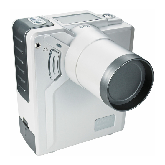
Page 24: Product Explanation
Product Explanation 6.3.1 Main body name Each part name of main body is as following. 2.35” LCD screen Time setting button Power button Product Label Hand strap X-RAY exposure Slide switch indicating lamp (Right) Low battery indicating lamp X-RAY exposure Remote control indicating lamp (Left) connector... -
Page 25: Ui Screen Composition And Functions
6.3.2 UI screen composition and functions ○ Name for each part on main control screen Status Teeth part of adult Status of Battery Adult image Exposure setting time Child image Exposure Button Status (Left, Right) Teeth part of child Figure 6.3 Name for each part on main control screen Adult image and teeth part of adult: Indicates recommended teeth part for adult by ... - Page 26 ○ Name for each part on environment Setting screen Setting value MENU change method change method Automatic power disconnection setting LCD back light time setting Exposure interval time Battery level UI version Total exposure counts Figure 6.4 Name for each part on environment setting screen MENU change method: Indicates change of menu location when pressing ‘▼’...
-
Page 27: Each Part Of The Buttons And Functions
6.3.3 Each part of the buttons and functions Slide switch ○ Each part of top side buttons and functions (State change switch) Power button Time setting button Figure 6.5 Name for each part on top side buttons Power button: It is used to turn on/off the device and as combination button to ... - Page 28 Table 6-1. Functions of time setting buttons CLASSIFICATION MAIN CONTROL SCREEN ENVIRONMENT SETTING SCREEN At power ON state Screen change Power button ON Power button + ▲button ▲ button use Exposure time increase Change value ▼ button use Exposure time decrease Menu change ◀...
- Page 29 ○ Front side exposure button and function Right exposure button Left exposure button Figure 6.7 Front side exposure button You can choose to use two buttons or left button only or right button only by setting up Function Screen. Exposing of X-ray with buzzer sound only while the button is being pressed and ...
-
Page 30: Name For Each Part On Battery Pack And Charging Devices
Name for each part on battery pack and charging devices 6.3.4 ○ Name for each part on battery pack Battery pack label Output terminal (+) Output terminal (-) Figure 6.8 Name for each part on battery pack Battery pack label: Indicates battery model name and precautions, manufacturer’s ... - Page 31 Charge indicating lamp: Indicates each status of charging or charge completion by different colors.(red: charging, green: charge completion, yellow: charge error) Charging terminals: Connect output terminals of battery pack to charging terminals of charging cradle and charge battery. Battery pack holder: Prevents battery pack from being dispatched when ...
- Page 32 AC input connector: Connect with AC input of power cord. Charging adapter label: Indicates model name and input/output condition, certification, serial numbers. AC power cord: Connect to AC power from external source WARNING Please keep the following rules whenever charging the battery pack. Use only appointed charger and battery pack.
-
Page 33: How To Use
7 How to use Power On/Off Insert enclosed battery to the right direction after opening battery cover at the bottom of main body. When pressing power button on the top of main body for 1 second, green light appears with buzzer sound around button and display is on with manufacturer’s logo as Figure 7.1. -
Page 34: X-Ray Exposure Positioning
Figure 7.2 Main control screen CHECK has automatic power shut off function in order to reduce battery DX3000 consumption. Automatic power shut off time is set for five minutes from the point of idling. Automatic power shut off time can be adjusted in setting option from 1 minute at minimum to 10 minutes at maximum. -
Page 35: Film Or Intraoral Sensor Positioning
7.2.2 Film or intraoral sensor positioning X-ray generated by can be detected by various detectors such as film, DX3000 intraoral sensor (digital), PSP and viewed. Place film or sensor on the teeth and hold it with finger not to be moved. ... -
Page 36: Dx3000 Positioning
7.2.3 DX3000 positioning The distance between the end of cone and patient must be within 20cm (8 inch) at least from Focal Spot (X-ray focus point). The target teeth have to be located at the center of cone in order to cover a whole ... - Page 37 The warning sound of X-ray exposure has three phases. The first phase is three short beep sound, the second phase is short melody sound, and the last phase is continuous beep sound. The X-ray only generates during the last phase. The warning sound of X-ray exposure set as a different transliteration for to ...
-
Page 38: X-Ray Exposure Time Set
7.3.2 X-RAY Exposure time set ’s x-ray exposure strength is fixed 60kV, 2mA and changeable by exposure DX3000 time set. ’s x-ray exposure time set is adjustable from 0.02 to 1.5 seconds. DX3000 Exposure time is adjustable by 0.01 second. ... - Page 39 Radiation Exposure Sensitivity Radiation exposure is a concern in all people of all ages, however, pediatrics are more sensitive to radiation exposure. Radiation risk is higher in young as they have more rapidly dividing cells than adults. The younger the patient, the more sensitive they are.
- Page 40 Table 7-2. Diagnostic Reference Level in Pediatrics 5-year old patient, Reference Dose Entrance Surface Dose Radiograph per SINGLE VIEW. [Unit: μGy] Skull AP 1500 Skull LAT 1000 CAUTION Exposure time set by teeth types can be variable by sensor type and film, distance to patient, image preference.
-
Page 41: Environment Setup
Environment setup 7.4.1 Environment setup screen After turning on device, keep pressing the power button and ‘▲’ button at the same time then the screen is switched to environment setting screen as Figure 7.4. Figure 7.4 Environment setup screen Press ‘▼’... - Page 42 Back-light Setting up LCD display back-light time is available. The default time set is 1 second and it is adjustable from 1 second to 10 seconds by 1 second. Exp Interval It indicates the interval of current exposure time. ...
-
Page 43: Wired Remote Controller
Wired remote controller 7.5.1 Wired remote controller usage Wired remote controller connector Wired remote controller jack Figure 7.5 Wired remote controller connection Connect using wired remote controller connector to wired remote controller connector on front part of device. Remote controller jack has to be DX3000 connected completely inside the connector for proper operation. -
Page 44: Back Scattered Shield
If button is pressed after exposure range is adjusted, X-RAY exposure is performed. Wired remote controller performs only exposure function, other settings and operations can be manipulated through device LCD screen. Back scattered shield 7.6.1 Mounting back scattered shield with Main body Disassemble radiation field cover at the edge of cone by spinning it DX3000... -
Page 45: Performance Of Back Scattered Shield
7.6.2 Performance of back scattered shield Figure 7.10 indicates the scattering radiation area which is changed by the use of back scattered shield. Back scatter shield limits scattering radiation area to subject’s area and reduces radiation dose by scattering radiation to doctor or operator except patient. Back Scatter Shield Patient Patient... -
Page 46: Battery
Battery 7.7.1 Mounting battery inside Main body Check if device power is OFF. DX3000 As shown in Figure 7.11, battery pack cover should be separated by pulling the cover backward after pulling displayed circle part Figure 7.8 Battery cover separation When battery cover is separated, battery pack should be inserted to main body. -
Page 47: Battery Level And Charging
Direction of Insertion Place label part to the main body’s bottom side and insert it by adjusting it to the rail of the main body Figure 7.9 Main body battery pack insertion 7.7.2 Battery level and charging ’s battery is a high output power and is designed to charge separately from DX3000 ... - Page 48 Battery level display and battery remain shown on right side of main control screen is as shown in Figure 7.14. If battery remain is between 0 ~ 15% section, replace with charged battery. 0~15% 16~45% 45~60% 61~100% Figure 7.10 Battery level display and remains When using device without battery replacement after ‘LOW’...
- Page 49 Battery charger consists of charging adapter and charging cradle. Charging cradle and adapter shape is shown in 7.15. Connect charger adapter DC plug to charging jack of back side of charging cradle. Use bundled AC power line to connect charger adapter, and connect to AC power code.
- Page 50 ① Connect charger DC plug to back side of jack on battery cradle ② Fit cradle connector and battery connector direction and settle from top ③ Start charging after precise settling Figure 7.13 Battery cradle and battery settling...
-
Page 51: Application Specification
Application specification 7.8.1 Intended medical indication The ‘Potable Dental X-RAY System’ (Model Name: DX3000, Product Name: iRay D3) is indicated for use only by trained and qualified dentists or dental technician for both adult and pediatric subjects for taking diagnostic intraoral dental X-RAY using conventional film or digital sensors. -
Page 52: Intended User Profile
7.8.3 Intended user profile Table 7-4. Intended user profile CONSIDERATIONS REQUIREMENT DESCRIPTION Dentist Dental technician Minimum Education Radiologic Technologist or person who has a license equal to it. Maximum Every user has knowledge in risk from X-ray exposure. Minimum Every user understands the regulatory information of ICRP. Knowledge Every user can set the exposure conditions Maximum... -
Page 53: Maintenance And Storage Method
8 Maintenance and storage method Maintenance and storage Device or battery pack in safe place so people other than qualified personnel are being able to have access. X-RAY radiation field that contacts patient directly should be maintained cleanly by wiping often with rubbing alcohol soaked wiping clothes. -
Page 54: Cleaning Procedure
Cleaning procedure Clean the external surface using a damp cloth and non oil-based detergent and disinfect it using a non-aggressive medical detergent. The spacer cone may be cleaned with cotton wool soaked with surgical alcohol. CAUTION Turn off the device before carrying out cleaning operations. Do not spray products directly on the device. -
Page 55: Charging Adaptor And Cradle Storage
8.3.2 Charging adaptor and cradle storage Take caution not to have foreign substance at cradle charge terminal, and wipe gently using cotton rod and soft clothes before storing. While not using the product, store after gently wiping. Take caution for battery pack (charger) not to contact with metallic substance ... -
Page 56: Maintenance Schedule
Maintenance Schedule 8.5.1 On-going Check Periodically review Section ‘1.1.1 Intended use’ for use and product labeling in order to verify understanding of indications for use for the DX3000. Section 2 Warning and instructions. Section 3 Caution and instructions. Section 4 ... -
Page 57: Annual User Check
8.5.2 Annual User Check Users should review the following material yearly, and be sure to record their results in the Maintenance Log Sheets located in Section 8.5.3. ① Power button verification: If you press the power button for 1 second, a beep will sound to signal that the machine has powered on. -
Page 58: Annual Calibration
Compare the result with the factory release parameters (indicated in the cart below). For results outside these parameters, discontinue use and contact DEXCOWIN. Table 8-1. Test Acceptance Ranges Exposure Time (mSec) -
Page 59: Maintenance Log Sheet
8.5.4 Maintenance Log Sheet Table 8-2. Maintenance Log Sheet Year 1 Year 2 Year 3 Year 4 Year 5 Year 6 Maintenance Test Date Date Date Date Date Date /Initial /Initial /Initial /Initial /Initial /Initial 1. Power button 2. Exposure button 3. -
Page 60: Inspection Items Before Repair Request
9 Inspection items before repair request Check items before requesting inspection If abnormality is found in product, confirm following items before inspection request. SYMPTOM STEPS TO TAKE After turning on Confirm battery is mounted correctly and replace with power, both sound or charged battery. - Page 61 SYMPTOM STEPS TO TAKE Check battery remaining, and replace with charged Low battery sign is battery pack. displayed on LCD Confirm if battery pack cover is closed and if it is screen open, check battery connection and close it by pushing cover all the way.
-
Page 62: Troubleshooting
Troubleshooting PROBLEM CAUSE SOLUTION No battery pack. Insert battery pack. Nothing lights up Low battery. Charge the battery. Generator is preparing an Wait for ready to X-ray exposure exposure. (about 5 seconds). Connect with wired remote control or change “Exp Key No X-ray emission “Remote”... -
Page 63: Product Specification And Product Warranty
10 Product specification and product warranty 10.1 Product Specification CLASSIFICATION DETAILS Product name Portable X-RAY System Input power Use the internal power supply (Battery) B-type application Cone Waterproof Rating IPX0 (General Equipment) Mode of operation Continuous operation Tube voltage 60 [kV] (Fixed) Tube current 2 [mA] (Fixed) Focal spot size... -
Page 64: Product Warranty
3. If breakdowns are due to incorrect usage or negligence, there will be charges for repair services even if within warranty period. 4. If you have other questions or product related inquiries, please contact Dexcowin Global Inc. customer service center. -
Page 65: Iray D3(Dx3000)Technical Document
11 iRay D3(DX3000)Technical document 11.1 High voltage generator 11.1.1 X-RAY Tube: D-081B 1. Manufacturer: TOSHIBA(Japan) 2. Electrical Characteristics Operating Tube Voltage ………………………………………………………………….65kV Focal Spot ……………………………………………………………………………………0.8 mm Input Power (at 1.0s) ……………………………………………………………………..600W 3. Mechanical Characteristics Dimensions Figure 11.1 Dimension of X-RAY tube... - Page 66 Target angle …………………………………………………………………………20 Degrees Material ……………………………………………………………………………………Tungsten Inherent Filtration ………………………At least 0.8 mmAl equivalent at 50kV Anode Thermal Characteristics Figure 11.2 Anode Heating/Cooling curve 4. Absolute Maximum and Minimum Ratings Maximum Tube Voltage ……………………………………………………….………..65 kV Maximum Inverse Tube Voltage…………………….………………..……………..75 kV ...
-
Page 67: Electromagnetic Compatibility
Figure 11.3 Maximum tube current curve by exposure time 11.2 Electromagnetic compatibility WARNING Other cables and accessories may negatively affect EMC performance. Use of other accessories may result in non-compliance. should not be used adjacent to or stacked with other equipment DX3000 and that if adjacent or stacked use is necessary, should be... - Page 68 installed and used in accordance with the instructions, may cause harmful interference to other devices in the vicinity. However, there is no guarantee that interference will not occur in a particular installation. If this equipment does cause harmful interference to other devices, which can be determined by turning the equipment off and on, the user is encouraged to try to correct the interference by one or more of the following measures.
-
Page 69: Electromagnetic Interference
11.2.1 Electromagnetic Interference Radiated emmition9electric field): 30 ~ 1000[MHz]. Min. limit margin: 4.9dB at 1000[MHz]. Table 11-2. Radiated emission data ATENNA READING CORRECTION FREQUENCY EMISSION LIMIT(10m) MARGIN TEST POL. LEVEL (AF+CL) [MHz] LEVEL [dBuV/m] [dBu/V] [H/V] [dBuV] [dB/m] Value 1000 H/V-... -
Page 70: Radiation Protection
11.3 Radiation Protection is IEC60601-1-3, IEC60601-2-28, IEC60601-2-65 from regulatory limits on DX3000 radiation safety and protection compliant. X-RAY operator must protect him/herself with a lead apron or wall. Must provide a patient protecting materials, such as a lead apron while operating. ... - Page 71 Table 11-5. Dose measured at extremity of 20 cm (8 inch) cone (0.49 ~ 1.35 sec) t[sec] D[mGy] t[sec] D[mGy] t[sec] D[mGy] t[sec] D[mGy] t[sec] D[mGy] 0.49 1.77 0.50 1.81 0.51 1.85 0.52 1.88 0.53 1.92 0.54 1.95 0.55 1.99 0.56 2.03 0.57...
-
Page 72: Dose Area Product
11.5 Dose area product Dose area product [mGy x ㎠]= nominal radiation output [mGy] x 26.4 [㎠] Exposed surface (A) - Standard cone: 58 [mm] Diameter (Round) - A = π x r = 3.14 x (29 [mm]) = 26.4 [㎠] Table 11-6. - Page 73 Table 11-7. Dose area product (0.84 ~ 1.35 sec) t[sec] t[sec] t[sec] t[sec] t[sec] 0.84 79.37 0.85 80.26 0.86 81.14 0.87 82.11 0.88 82.99 0.89 84.01 0.90 84,93 0.91 85.78 0.92 86.66 0.93 87.50 0.94 88.39 0.95 89.32 0.96 90.17 0.97 91.05 0.98...
-
Page 74: Leakage Radiation
11.6 Leakage Radiation 11.6.1 Measurement in 1[m] from focal spot The following is leakage radiation at 1[m] from focal spot. Unit: [mR/h, (mGy/h)] ○ Right ○ Rear-right ○ Front-right Horizontal direction ○ ○ Rear-left ○ Front-left ○ Left Vertical direction ○... -
Page 75: Measurement In 1[Cm] From Case Surface
Table 11-8. Leakage radiation at 1[m] from the focal spot Directions Values ○ Test 1 Test 2 Test 3 Test 4 Test 5 Test 6 ○ Bottom ○ Left ○ Right ○ Front ○ Rear ○ Front-left ○ Front-right ○ Rear-left ○... - Page 76 ○ ○ ○ ○ ○ ○ ○ ○ ○ ○ ○ ○ ○ Figure 11.5 Measurement points in 1[cm] from case surface...
- Page 77 Table11-9. Leakage radiation at 1[cm] from case surface TEST 1 TEST 2 TEST 3 NUMBER mR/h mGy/h mR/h mGy/h mR/h mGy/h 3.93 0.0393 3.95 0.0395 3.95 0.0395 2.81 0.0281 2.79 0.0279 2.82 0.0282 3.05 0.0305 3.08 0.0308 3.06 0.0306 4.25 0.0425 4.27 0.0427...
-
Page 78: Stray Radiation
11.7 Stray Radiation 11.7.1 Set the significant zone of occupancy Personal protection equipment such as lead apron must be worn when shooting x- ray in the significant zone of occupancy as Figure 11.6. 200[cm] 60[cm] 60[cm] Figure 11.6 Significant zone of occupancy... -
Page 79: Test Method And Result Of Stray Radiation
11.7.2 Test method and result of stray radiation The device and environment setup for measurement of stray radiation is Figure 11.7. After all setups, measure the stray radiation in the significant zone of occupancy. Considering use environment of device, set up distance between Focal spot and ... - Page 80 The measurement results of stray radiation at 20cm from Focal spot are as Table 11-10. Table 11-10. Stray radiation at 20[cm] from focal spot POINT A POINT B POINT C POINT D POINT E POINT F 0 cm 0.648 0.651 0.679 0.679...
- Page 81 The measurement results of stray radiation at 25cm from Focal spot are as Table 11-11. Table 11-11. Stray radiation at 25[cm] from focal spot POINT A POINT B POINT C POINT D POINT E POINT F 0 cm 0.968 0.714 0.684 0.863...
-
Page 82: Stay Radiation With Back Scattered Shield Application
11.7.3 Stay radiation with back scattered shield application Attach back scattered shield as Figure 11.10 and measure stray radiation. Considering use environment of device, set up distance between Focal spot and water equivalent phantom as 20cm and 25cm and measure. The measuring points in the significant zone of occupancy are every 10cm point ... - Page 83 The measurement results of stray radiation at 20cm from Focal spot are as Table 11-12. Table 11-12. Stray radiation at 20[cm] from focal spot with back scattered shield POINT A POINT B POINT C POINT D POINT E POINT F 0 cm 0.374 0.393...
- Page 84 The measurement results of stray radiation at 25cm from Focal spot are as Table 11-13. Table 11-13. Stray radiation at 25[cm] from focal spot with back scattered shield POINT A POINT B POINT C POINT D POINT E POINT F 0 cm 0.323 0.932...
Need help?
Do you have a question about the iRayD3 and is the answer not in the manual?
Questions and answers