
Related Manuals for concept 2 DYNO


Summary of Contents for concept 2 DYNO
- Page 3 DYNO ASSEMBLY INSTRUCTIONS Open the three boxes and remove all the parts. Lay out the parts as shown below before beginning assembly. Call Concept2 if any parts are missing. Parts List Pull Side Seat PN5401 1 Monorail Assembly PN5100 10 Pull Side Seat Brackets...
- Page 4 Tools required • Phillips screwdriver • Flat blade screwdriver • (2) 9/16” box end wrench (included) • 1/2” box end wrench (included) • rubber mallett (not shown) may be helpful 2. Attach the Push Side Foot Assembly to the Flywheel Assembly using two of the 3/8” by 5/8” bolts.
- Page 5 5. Route the Bungee Cord around the bungee cord pulley at the angled end of the monorail. 7a. Take the other end of the Bungee Cord, coming 6. Take the end of the Bungee Cord that is coming off the bottom of the pulley, and attach it to the off the top of the pulley and attach it to the loose Chain Connector Plate as shown.
- Page 6 8a. Attach the Push Side Seat Assembly to the Flywheel/Monorail Assembly using four of the 3/8” by 5/8” bolts and the top holes you didn’t Hint: You may also have to loosen the screws that use in Step 4b. Note orientation of the seat attach the seat to the Seat Brackets.
- Page 7 Attach the assembled Pull Side Leg and the Pull Side Seat Brackets to the Monorail using two 3/8” by 2 5/8” bolts and two 3/8” nuts. This is the trickiest step in the assembly because you have to align six holes and get one bolt through them all.
- Page 8 13a. Roll the Carriage Assembly on the Monorail so that its holes line up with the holes in the Chain Connector Plate. You will need to press the plate up into the slot to get it between the bottom rollers of the Carriage. 13b.
- Page 9 16b. Attach the Monitor Assembly to the top of the Mast using the two 1/4” by 21/2” screws and 16a. Route the Monitor Cable through the center two 1/4” nuts. It doesn’t matter which way you hole in the Monitor Assembly. insert the bolts.
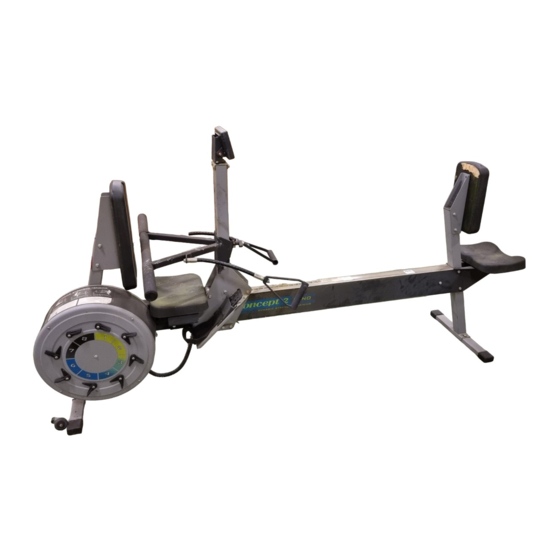
- Page 10 Push side, the smaller goes on the Pull side. Use two 3/8” by 2 5/8” bolts and 3/8” nuts for each Seat Back. 20. Refer to this photo to make sure you have assembled your Dyno correctly. Please read the User’s Manual before you get started.
- Page 12 MORRISVILLE, VERMONT USA 05661 EMAIL:ROWING@CONCEPT2.COM WEB:WWW.CONCEPT2.COM...
Need help?
Do you have a question about the DYNO and is the answer not in the manual?
Questions and answers