Table of Contents
Advertisement
NORTEK GLOBAL HVAC, LLC
Owner's Manual
Please read this owner's manual carefully before operation and retain for future reference.
Specifications & illustrations subject to change without notice or incurring obligations.
If you have lost the owner's manual, please visit www.NortekHVAC.com for electronic version.
Wired Remote Controller
WRC4
Original Instructions
Advertisement
Table of Contents

Related Manuals for Nortek WRC4


Summary of Contents for Nortek WRC4
- Page 1 NORTEK GLOBAL HVAC, LLC Wired Remote Controller WRC4 Owner's Manual Original Instructions Please read this owner's manual carefully before operation and retain for future reference. Specifications & illustrations subject to change without notice or incurring obligations. If you have lost the owner’s manual, please visit www.NortekHVAC.com for electronic version.
- Page 2 User Notice ◆ Never install the wired remote controller in the moist circumstance or expose it directly under the sunlight. ◆ Never beat, throw, and frequently disassemble the wired remote controller and the wireless remote controller. Never operate the wired remote controller and the wireless remote controller with wet hands. ◆...
-
Page 3: Table Of Contents
Contents Wired Remote Controller WRC4 ..............1 1 Symbols on LCD ................... 1 1.1 Outside View of the Wired Remote Controller ............1 1.2 LCD of the Wired Remote Controller ..............1 2 Buttons ......................2 2.1 Buttons on the Wired Remote Controller .............. 2 2.2 Function of the Buttons .................. -
Page 4: Wired Remote Controller Wrc4
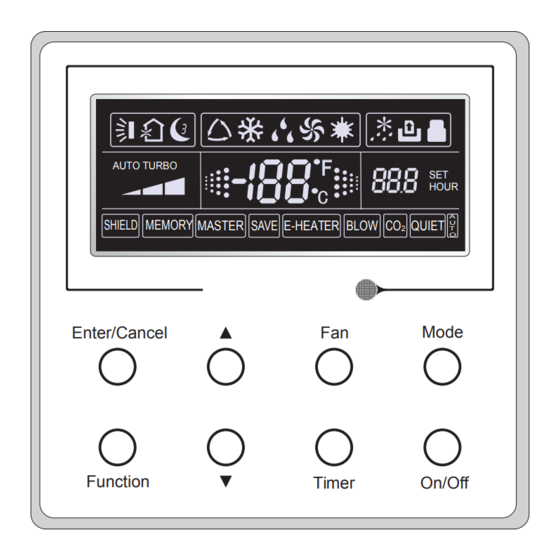
Wired Remote Controller WRC4 Wired Remote Controller WRC4 1 Symbols on LCD 1.1 Outside View of the Wired Remote Controller AUTO TURBO HOUR SHIELD MEMORY MASTER SAVE E-HEATER BLOW QUIET Mode Enter/Cancel Enter/cancel Function Timer On/Off Fig.1 Outside View of the Wired Remote Controller 1.2 LCD of the Wired Remote Controller... -
Page 5: Buttons
Wired Remote Controller WRC4 Table 1 Symbols Description Swing function. Sleep function (Only sleep 1). Running modes of the indoor unit (Cooling, Dry, Fan and Heating). Defrosting function for the outdoor unit. Gate-control function. Lock function. High, middle, low or auto fan speed of the indoor unit. -
Page 6: Function Of The Buttons
Wired Remote Controller WRC4 2.2 Function of the Buttons Table 2 Name Function Enter/Cancel Function selection and cancellation. ▲ ① Running temperature setting of the indoor unit, range:61~86°F(16~30℃). ② Timer setting, range:0.5-24 hr. ▼ Setting of the high/middle/low/auto fan speed. -
Page 7: Operation Instructions
Wired Remote Controller WRC4 3 Operation Instructions 3.1 On/Off Press On/Off to turn on the unit and turn it off by another press. Note: The state shown in Fig.4 indicates the “Off” state of the unit after power on. The state shown in Fig.5 indicates the “On”... -
Page 8: Fan Setting
Wired Remote Controller WRC4 Fig.6 3.4 Fan Setting Under the “On”/”Off” state of the unit, press Fan and then fan speed of the indoor unit will change circularly as shown in Fig.7. Middle High AUTO Enter/Cancel Mode Function Timer On/Off Fig.7... - Page 9 Wired Remote Controller WRC4 Fig. 8 Timer off Setting under the “On” State of the Unit Timer range: 0.5-24hr. Every press of ▲or ▼ will make the set time increased or decreased by 0.5hr. If either of them is pressed continuously, the set time will increase/ decrease by 0.5hr every...
-
Page 10: Swing Setting
Wired Remote Controller WRC4 3.6 Swing Setting Swing On: Press Function under on state of the unit to activate the swing function. In this case, Swing Off: When the Swing function is on, press Function to enter the Swing setting interface, with blinking. -
Page 11: Sleep Setting
Wired Remote Controller WRC4 3.7 Sleep Setting Sleep on: Press Function under on state of the unit till the unit enters the Sleep setting Sleep off: When the Sleep function is activated, press Function to enter the Sleep setting interface. After that, press Enter/Cancel to can this function. -
Page 12: Turbo Setting
Wired Remote Controller WRC4 3.8 Turbo Setting Turbo function: The unit at the high fan speed can realize quick cooling or heating so that the room temperature can quickly approach the setting value. In the Cooling or Heating mode, press Function till the unit enters the Turbo setting interface When the Turbo function is activated, press Function to enter the Turbo setting interface and then press Enter/Cancel to cancel this function. -
Page 13: E-Heater Setting
Wired Remote Controller WRC4 3.9 E-heater Setting E-heater (auxiliary electric heating function): In the Heating mode, E-heater is allowed to be Once the wired remote controller or the remote controller enters the Heating mode, this function will be turned on automatically. -
Page 14: Blow Setting
Wired Remote Controller WRC4 3.10 Blow Setting Blow function: After the unit is turned off, the water in evaporator of indoor unit will be automatically evaporated to avoid mildew. In the Cooling or Dry mode, press Function till the unit enters the Blow setting interface and then press Enter/Cancel to active this function. -
Page 15: Other Functions
Wired Remote Controller WRC4 3.11 Other Functions (1). Lock Upon startup of the unit without malfunction or under the “Off” state of the unit, press ▲ and ▼ at the same time for 5s till the wired remote controller enters the Lock function. In this case, LCD displays . -
Page 16: Installation And Dismantlement
Wired Remote Controller WRC4 (4). Selection of the Fan Speed go to the commissioning status, and then adjust the display in the temperature display area to 01 through the button “Mode” and adjust the setting of the fan speed, which comes to two options. - Page 17 Wired Remote Controller WRC4 Note:CN1 is 485 communication interface and it used for connecting the 4-core communication wire. These two needle stands(CN2、CN3) are used for connecting the smart zone controller. There is no sequence for these two needle stands. You can connect one or two needle stand(s) basing on the requirement.
- Page 18 DIP switch. There is a 2-bit DIP switch on the main board of wired controller WRC4. As for the last #n wired controller in the control system, the 1-bit and the 2-bit of the DIP switch should be manually pulled to position “on” and position “off” respectively. The DIP switches of other wired controllers should be kept at the initial ex-factory status (1-bit and 2-bit are set at position “off”).
-
Page 19: Dismantlement Of The Wired Remote Controller
Wired Remote Controller WRC4 cord and connection lines between the indoor and outdoor unit, with a minimum interval of 20cm, otherwise the communication of the unit will probably work abnormally. If the air conditioning unit is installed where is vulnerable to electromagnetic interference, ②... - Page 20 Wired Remote Controller WRC4 Table 4 Meaning of Each Error Error Error Error Error Code Code Return air temperature sensor open/short Drive board communication error circuited evaporator temperature sensor open/short Compressor overheating protection circuited Indoor unit liquid valve temperature sensor...
- Page 24 Specifications & illustrations subject to change without notice or incurring obligations. O’Fallon, MO (08/18) © Nortek Global HVAC, LLC 2018. All Rights Reserved. 198F-0818 66129929868...
Need help?
Do you have a question about the WRC4 and is the answer not in the manual?
Questions and answers