
Subscribe to Our Youtube Channel
Related Manuals for KRAL EKL 11


Summary of Contents for KRAL EKL 11
- Page 1 Operation instructions KRAL pump stations. EKL/EKS 11/12/13 OIK 10en-GB Edition 2021-06 Original instructions www.kral.at...
-
Page 2: Table Of Contents
Table of contents 1 About this document ............. 3 Protecting the pump station against pressure peaks ... 18 General information ............ 3 Removing the pump station ......... 19 Associated documents .......... 3 9 Connection .............. 20 Target groups .............. 3 Dangers during connection work ......... 20 Symbols................. 3 Connecting the pump station to the pipe system .. 20 1.4.1... -
Page 3: About This Document
1 About this document 1.1 General information 1 About this document 1.1 General information These instructions form part of the product and must be kept for future reference. Furthermore please observe the associated documents. 1.2 Associated documents o Declaration of conformity according to EU Directive 2006/42/EC o Manufacturer's declaration according to EU Directive 2014/68/EU o Corresponding operating instructions of the pump o Technical documentation of the supplied components... -
Page 4: Danger Signs
1 About this document 1.4 Symbols 1.4.2 Danger signs Meaning Source and possible consequences of non-observance Electrical voltage Electrical voltage causes serious physical injury or death. Raised load Falling objects can result in serious physical injury or death. Heavy load Heavy loads can result in serious back problems. -
Page 5: Safety
2 Safety 2.1 Proper use Meaning Possible consequences of non-observance Close fitting work clothing Serious physical injury through clothes being drawn in Slip resistant safety boots Serious foot injury through falling or toppling parts and seri- ous physical injury through falling 2 Safety 2.1 Proper use o Use the pump station solely for transporting lubricating liquids that are chemically neutral and that... -
Page 6: Safety Instructions
3 Identification 2.4 Safety instructions 2.4 Safety instructions 2.4.1 Fundamental safety instructions The following safety instructions must be observed strictly: o Read these operating instructions carefully and observe them. o Read the operating instructions of the components carefully and observe them. o Have work only carried out by qualified personnel/trained personnel. -
Page 7: Rating Plate
ºC ¹ Serial number max. / p max. mm²/s Type Jahr | Year Gewicht | Weight KRAL GmbH, 6890 Lustenau, Austria KRAL GmbH, 6890 Lustenau, Austria www.kral.at www.kral.at Article number Fig. 2: Rating plate Differential pressure Nominal delivery rate Rated speed... -
Page 8: Sound Pressure Level
4 Technical data 4.3 Sound pressure level 4.3 Sound pressure level Guide values at 1 m distance, 1450 min , 10 bar Size Sound pressure level ±3 [dB(A)] Pump Motor Pump unit 240 – 1000 50.0 42.0 51.0 1800 – 2300 52.0 44.0 54.0 3200 – 4000 55.0 50.0 56.0 6000... -
Page 9: Mesh Width Strainer/Filter
4 Technical data 4.5 Mesh width strainer/filter Size of pump station EKS Size of pump KFN Unit Motor output [kW] 0.25 0.25 0.25 Delivery rate at 6 mm o 50 Hz, 1450 min o 3 bar [l/h] o 6 bar [l/h] o 60 Hz, 1750 min o 3 bar [l/h] o 6 bar... -
Page 10: Function Description
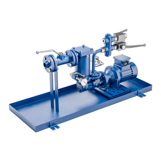
5 Function description 5.1 Structure of standard version 5 Function description 5.1 Structure of standard version Fig. 3: EKL/EKS 11 Fig. 4: EKL/EKS 12 10 17 Fig. 5: EKL/EKS 13 Pump unit Base frame Strainer Deaerator venting Deaerator with integrated strainer Suction-side pressure gauge Ball valve Pressure-side pressure gauge Pressure maintaining valve... -
Page 11: Structure Of Special Design
5 Function description 5.2 Structure of special design 5.2 Structure of special design Fig. 6: EKS 11 special design Pump unit Suction-side pressure gauge Strainer Pressure-side pressure gauge Base frame Overflow valve pump 5.3 Functional principle The pump station of the EKL/EKS series is a fuel oil transfer pump station and in the basic module con- sists of a screw pump of the series KFN 1, large-area strainer 2, suction-side and pressure-side ball valves 6 as well as shut-off pressure gauges 17, 18 on the suction side and pressure side. -
Page 12: Pulsation Damper
5 Function description 5.5 Pulsation damper 5.5 Pulsation damper As a mechanical regulating valve, the pressure maintaining valve has a certain sluggishness. There- fore rapid changes in the flow rate (for example usage of rapid switching valves, starting of the pump without soft start) and rigid pipe systems can result in brief pressure peaks. -
Page 13: Options For Standard Version
5 Function description 5.8 Options for standard version The pump station is equipped with one or two strainers as standard. However, these are not capable of separating larger amounts of soiling occurring regularly or abrasive fine particles. If such operating con- ditions occur, the station has to be protected additionally by a correspondingly dimensioned operating filter. -
Page 14: Heating System (Optional)
6 Transportation, storage 5.10 Heating system (optional) 5.10 Heating system (optional) 5.10.1 Possible types of heating The pump station can optionally be equipped with a heating system. The manufacturer recommends a heating system at high-viscosity pumped liquids that do not flow sufficiently if not heated. This can res- ult in excessive wattage or in problems arising through cavitation or sealing. -
Page 15: Unpacking And Checking The State Of Delivery
6 Transportation, storage 6.3 Unpacking and checking the state of delivery 6.3 Unpacking and checking the state of delivery Upon delivery unpack the pump station and check it for damage during transportation. Report damage during transportation immediately to the manufacturer. Dispose of packaging material in accordance with the locally applicable regulations. -
Page 16: Preservation
7 Preservation 7.1 Preservation table ATTENTION Damage to equipment and corrosion if stored improperly and during longer standstills. ► Protect the pump station against damage, heat, sunlight, dust, moisture and magnetic fields. ► Protect against corrosion during longer standstill. ► Observe measures for storing and preservation. Store cool and dry and protect against sunlight. -
Page 17: Removing The Preservation
8 Installation, removal 7.4 Removing the preservation 7.4 Removing the preservation o Trained personnel Personnel qualification: o Work clothing Personal protective equipment: o Protective gloves o Safety boots Aids: o Solvent o Steam-jet cleaning device with wax-dissolving additives o Collection tank CAUTION Risk of injury through discharging preservative. -
Page 18: Mounting The Pump Station
8 Installation, removal 8.3 Mounting the pump station 8.3 Mounting the pump station Notice Soiling in the pipe system impairs the service life of the pump station. If the pipe system is flushed us- ing the pump station during the initial commissioning, an additional commissioning filter has to be in- stalled temporarily before the pump station. -
Page 19: Removing The Pump Station
8 Installation, removal 8.5 Removing the pump station 8.5 Removing the pump station o Transport personnel Personnel qualification: o Fitter o Electrician o Work clothing Personal protective equipment: o Protective helmet o Face protection o Protective gloves o Safety boots o Mobile crane, forklift, hoisting equipment Aids: o Solvents or industrial cleaners suitable for the pumped liquid... -
Page 20: Connection
9 Connection 9.1 Dangers during connection work 9 Connection 9.1 Dangers during connection work The following safety instructions must be observed strictly: o Have all work on the pump station and pipe system only carried out by authorized qualified per- sonnel. -
Page 21: Pipe Screwed Connection
9 Connection 9.2 Connecting the pump station to the pipe system ATTENTION Damage to device through impurity in the pipe system. ► During welding work attach protective covers in front of the connecting flanges. ► Ensure when welding that welding beads and abrasive dust cannot get into the pipe system and the pump station. -
Page 22: Connecting The Pump Station To The Power Supply
10 Operation 9.3 Connecting the pump station to the power supply Fig. 15: Pipe screwed connection Apply lubricating oil lightly to the progressive ring 2 and pipe 3. Slide the union nut 1 and progressive ring 2 over the pipe end. Ensure that the direction of the progressive ring is correct in the process. -
Page 23: Commissioning
10 Operation 10.2 Commissioning 10.2 Commissioning 10.2.1 Cleaning the pipe system Notice Soiling in the pipe system impairs the service life of the pump station. If the pipe system is flushed us- ing the pump station during the initial commissioning, an additional commissioning filter has to be in- stalled temporarily before the pump station. -
Page 24: Checking The Direction Of Rotation
10 Operation 10.2 Commissioning DANGER Risk of death through emitted pumped liquid. Pumped liquids can be hot, poisonous, combustible and caustic and can spray out under high pres- sure. ► Observe the operating instructions of the pump. ► Wear personal protective clothing during all the work. Ensure face protection. ►... -
Page 25: Venting The Deaerator
10 Operation 10.2 Commissioning WARNING Risk of injury through emitted pumped liquid. Pumped liquids can be hot, poisonous, combustible and caustic. ► Wear personal protective clothing during all the work. Ensure face protection. ► Collect any discharging pumped liquid safely and dispose of it in an environmentally compatible manner in accordance with the applicable local regulations. -
Page 26: During Operation
10 Operation 10.3 During operation 10.3 During operation 10.3.1 Checking the operating pressure Personnel qualification: o Trained personnel Fig. 16: Pressure gauge shut-off valves closed/open - principle diagram ATTENTION Leak in the pressure gauge through permanently opened pressure gauge shut-off valve. ►... -
Page 27: Switching Off The Pump Station
10 Operation 10.4 Decommissioning 10.3.4 Switching off the pump station Personnel qualification: o Trained personnel ATTENTION Seal damage through pressurizing during standstill. ► Ensure that the maximum permissible system pressure is not exceeded. Switch off the motors. Close the pressure- and suction-side shut-off devices. 10.4 Decommissioning 10.4.1 Taking the pump station out of operation Personnel qualification:... -
Page 28: Recommissioning
11 Maintenance 10.5 Recommissioning Behaviour of the pumped liquid Duration of the operation interruption Short Long o No corrosive burden o Remains liquid – Drain the pump station. o Corrosive burden Preserve the pump station. Tab. 13: Measures depending on the behaviour of the pumped liquid Drain the pump station via the pressure line, suction line, vent screws and screw plugs. -
Page 29: Maintaining The Strainers
12 Servicing 11.4 Maintaining the strainers 11.4 Maintaining the strainers o Fitter Personnel qualification: o Work clothing Personal protective equipment: o Protective gloves o Safety boots Check the strainers visually and acoustically every four weeks. In the case of a clear pressure drop clean the strainers Ä Servicing, Page 29. 12 Servicing 12.1 Dangers during servicing The following safety instructions must be observed strictly:... -
Page 30: Replacing The Pump
12 Servicing 12.4 Replacing the pump DANGER Risk of death resulting from electric shock. ► Ensure that the electrical power supply is de-energized and is secured against being switched back on. ► Before commissioning ensure correct grounding and equipotential bonding. ►... -
Page 31: Cleaning The Strainer
12 Servicing 12.5 Cleaning the strainer Fig. 17: Strainer (left) / Deaerator with integrated strainer (right) Switch off the motor and secure it against being switched back on. Close the pressure-side and suction-side shut-off devices. Open the vent screws at the pump flange by a maximum of 2 rotations in order to reduce the in- ternal pressure in the housing. -
Page 32: Disposal
13 Disposal 13.1 Dismantling and disposing of the pump station Fig. 18: Strainer (left) / Deaerator with integrated strainer (right) Close the pressure-side and suction-side shut-off devices. Open the vent screw 6/vent cock 7 carefully in order to reduce the pressure in the strainer. Drain the strainer by means of the drain screw 6. -
Page 33: Troubleshooting
14 Troubleshooting 14.1 Possible faults Recycle iron parts. 14 Troubleshooting 14.1 Possible faults Faults can have different causes. The following tables list the symptoms of a fault, the possible causes and measures for troubleshooting. Identifica- Fault tion No pump suction Delivery rate too low Pump too loud Motor overload... - Page 34 14 Troubleshooting 14.2 Troubleshooting Fault identification Cause Remedy – 2 3 – 5 – – Airlock/gas in the pumped liquid Test the pipe system for air admission, replace leaking parts. Reduce the suction head. -or- Increase the inlet pressure. – 2 – 4 – – – Speed/frequency/voltage of the motor false Ensure that the motor frequency and voltage match the operating voltage.
- Page 35 14 Troubleshooting 14.2 Troubleshooting Fault identification Cause Remedy 1 2 3 4 5 – – Cold start when delivering high-viscosity liquids Install the heating system. – – – – – – 7 Differential pressure is too high and has overloaded the idle screws Contact the manufacturer.
-
Page 36: Spare Parts
15 Spare parts 15.1 Overview 15 Spare parts 15.1 Overview 407.2 407.1 606.2 729.2 729.1 729.1 606.1 Fig. 19: EKL/EKS 11 407.2 407.2 606.2 407.1 729.2 729.1 729.1 606.1 Fig. 20: EKL/EKS 12 Operation instructions OIK 10en-GB Edition 2021-06... - Page 37 15 Spare parts 15.1 Overview 407.2 407.2 407.1 606.2 729.2 729.1 729.1 606.1 Fig. 21: EKL/EKS 13 729.1 729.2 606.1 180 526 606.2 Fig. 22: EKS 11 special design 405.4 408.4 405.3 408.3 408.2 408.5 405.2 408.3 405.1 408.1 Fig. 23: Strainer (left) / Deaerator with integrated strainer (right) Operation instructions OIK 10en-GB Edition 2021-06...
-
Page 38: Appendix
16 Appendix 16.1 Tightening torques for screws with metric screw threads with and without wedge lock washers Item No. Part Item No. Part Pump bracket 408.2 Conical spring Base frame with oil pan 408.3 O-ring Strainer 408.4 Strainer cover 405.1 Strainer insert 408.5 Vent cock... -
Page 39: Tightening Torques For Screw Plugs With Thread Measured In Inches And Elastomer Seal
16 Appendix 16.2 Tightening torques for screw plugs with thread measured in inches and elastomer seal 16.2 Tightening torques for screw plugs with thread measured in inches and elastomer seal Notice In the case of galvanised screw plugs and screw plugs made of stainless steel the inner thread and outer thread have to be greased thorough before mounting in order to prevent threads from seizing. - Page 40 KRAL GmbH, 6890 Lustenau, Austria, Tel.: +43/5577/86644-0, E-Mail: kral@kral.at www.kral.at...
Need help?
Do you have a question about the EKL 11 and is the answer not in the manual?
Questions and answers