Advertisement
Quick Links
Warsaw
BEFORE installation, fully read
the USER MANUAL.
Proceed with installation only after
gaining a full understanding of this Manual.
For safety reasons during installation and use of the
device, it is advisable to follow the recommendations and
warnings included in this Manual and marked with the
depicted symbol.
The Manual should be stored for the Digital Gas Detection
Systems' User perusal.
1.
Purpose
2. Technical specifications
3.
Description and assembly
4.
MDD installation within the system
5.
MDD configuration
6.
Digital Gas Detection System launch
6.8 PROBLEM ? Useful information
6.9 Installation and launch recommendations
7.
Maintenance/operation
8.
Storing the MDD
©gazex 2018. All rights reserved. No part of these pages, either text or image may be copied or distributed without GAZEX's permission.
The gazex logo and name as well as dex, ASBIG, Aktywny System Bezpieczeństwa Instalacji Gazowej are registered trademarks of the GAZEX
MDD-256/T Control Unit User Manual
Digital
Control
Unit
USER MANUAL
Issue 1W21en
PRODUCER:
Work and live SAFER with us !
M
D
M
D
Issue 1W21en
©gazex'2018 v1806
D
2
5
6
-
D
-
2
5
6
[ series W2 ]
p. 2
3
4
5
8
15
18
19
22
22
Page 1 / 22
T
/
/
T
company.
©gazex
Advertisement

Related Manuals for gazex MDD-256/T


Summary of Contents for gazex MDD-256/T
- Page 1 PRODUCER: ©gazex 2018. All rights reserved. No part of these pages, either text or image may be copied or distributed without GAZEX’s permission. The gazex logo and name as well as dex, ASBIG, Aktywny System Bezpieczeństwa Instalacji Gazowej are registered trademarks of the GAZEX company.
- Page 2 In next parts of this Manual, the MDD-256/T control module will be referred to as the "MDD" module. Features and functions performed by the MDD: controls and manages the network of digital detectors and digital modules;...
-
Page 3: Connection Diagram
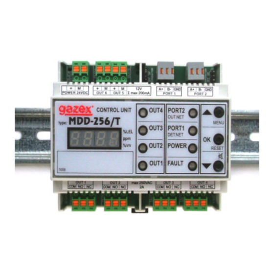
106 x 90 x 65 mm, width x height x depth (width of 6 mod.); ca. 0,2kg Casing polystyrene, IP20; for installation in electrical switchboards on a 35 mm rail MDD-256/T Control Unit User Manual Issue 1W21en Page 3 / 22... - Page 4 Lights for output status Terminal block of the relay outputs Module or detector network status display Measurement units (for measuring detectors) User’s description field Pic.3.1 MDD-256/T front panel view (rail mounting position) optical-acoustic signalling device light siren 230V~ POWER SUPPLY RS-485 DET.NET network...
- Page 5 “hurt” the conductors. Using a knife or other sharp tool for this purpose may result in a local reduction of the cable conductor cross-section, which when bent MDD-256/T Control Unit User Manual Issue 1W21en Page 5 / 22 ©gazex’2018 v1806...
- Page 6 Caution: No other connection of multiple bus lines by twisting the lines is permitted, as it is very likely that the lines will break off when twisted or loosened in the future. TABLE 4.2.2. Suggested use of the FTP / STP cables (colour scheme used on labels of all RS-485 ports made by GAZEX) WIRE COLOUR FUNCTION...
- Page 7 4.2.6 If it is necessary to use additional devices inside the [DET.NET] bus, e.g. fiber optic converters, the choice of the device should be consulted with the GAZEX Technical Support Department.
- Page 8 L.rmm], where "r" is the last digit of the year; "mm" - a month) - this information may be required when contacting the GAZEX Technical Support Department. The individual lamps light up and go out one after the other. During this time, the module settings are initialised.
- Page 9 Selecting the detector number from [ d.001 ] ÷ [ d.224 ]. Select a number that matches the slave address of the detector. Any changes will only apply to the selected detector. MDD-256/T Control Unit User Manual Issue 1W21en Page 9 / 22...
- Page 10 Here, the user can configure the parameters of the executive devices, e.g. MDD-L32/T or MDD-R4/T modules, on a common DET.NET bus. These modules are controlled by the MDD-256/T (reserved network addresses above [A.224]). The MDD refreshes the register of executive devices each time it queries the entire detector network.
- Page 11 10) The MDD automatically changes the slave address to the next one (A.002) and temporarily assigns it to the remaining detectors. 11) The steps listed in points 2÷6 are repeated. MDD-256/T Control Unit User Manual Issue 1W21en Page 11 / 22...
- Page 12 [└┐003 ] ÷ [└┐900 ] seconds. MDD-256/T Control Unit User Manual Issue 1W21en Page 12 / 22...
- Page 13 (Fault status is available via PORT2 after polling by the control module). Modes [ Zo.12 ] and [ Zo.11 ] are recommended in one-way detector networks, e.g. the DD detector type. MDD-256/T Control Unit User Manual Issue 1W21en Page 13 / 22...
- Page 14 [ LooP ] – setting it to [ L.YES ] loops the slave address browsing procedure. When the entire detector network is displayed, the MDD automatically restarts the display from the beginning. The display can be interrupted by pressing the [▼] key for approx. 2 seconds. MDD-256/T Control Unit User Manual Issue 1W21en Page 14 / 22...
- Page 15 All devices for the Digital Gas Detection System equipped with RS-485 communication ports are supplied by GAZEX with communication switched off as a default setting (set to "zero" address). In this state, the devices will not respond to the control module's queries until the control module has assigned an individual address to them.
- Page 16 If the detector status display is enabled, the current device status is displayed when each slave address is displayed. When all addresses have been displayed, the MDD returns to normal operation. MDD-256/T Control Unit User Manual Issue 1W21en Page 16 / 22...
- Page 17 Results of the control or the launch should be entered into Periodic Control Protocol If the test result is positive, the Digital Gas Detection System may be considered as operational. MDD-256/T Control Unit User Manual Issue 1W21en Page 17 / 22...
- Page 18 DET.NET bus devices dozen seconds, then minute (for low-calibration the alarms disappear detectors) If you notice effects other then the above mentioned contact an Authorised Service or the Producer. MDD-256/T Control Unit User Manual Issue 1W21en Page 18 / 22 ©gazex’2018 v1806...
- Page 19 In this case, return to the previous device, check again and correct the connections of the cables coming out to the last device, or check the wiring status between the devices. MDD-256/T Control Unit User Manual Issue 1W21en Page 19 / 22...
- Page 20 If the observed signalling (or lack of it) indicates an incorrect voltage supply for the selected devices, the cause should be found and the fault corrected. Table 6.9.4 describes typical problems with powering the device bus. MDD-256/T Control Unit User Manual Issue 1W21en Page 20 / 22...
- Page 21 Check the routing of the bus cables to ensure that they are not routed in parallel with other cables that may have an increased risk of interference. If you notice effects other then the above mentioned contact an Authorised Service or the Producer. MDD-256/T Control Unit User Manual Issue 1W21en Page 21 / 22...
-
Page 22: Maintenance/Operation
(durability depends on length of storage time without power supply). After 10 years from the production date, it is recommended to replace the battery with a new one - replacement only by the Manufacturer. MDD-256/T Control Unit User Manual Issue 1W21en Page 22 / 22...
Need help?
Do you have a question about the MDD-256/T and is the answer not in the manual?
Questions and answers