Advertisement
Quick Links
Warsaw
BEFORE installation, fully read
the USER MANUAL.
Proceed with installation only after
gaining a full understanding of this Manual.
For safety reasons during
installation and use of the device, it
is advisable to follow the recommendations and
warnings included in this Manual and marked with the depicted
symbol.
The Manual should be stored for the Gas Detection Systems'
User perusal.
1.
Purpose
2.
Technical specifications
3.
Description and assembly
4.
MDP installation within the system
5.
MDP configuration
6.
Launching of the MDP in the system
6.6 PROBLEM ? Useful information
7.
Maintenance/operation
8.
Storing the MDP
©gazex 2016. All rights reserved. No part of these pages, either text or image may be copied or distributed without GAZEX's permission.
The gazex logo and name as well as dex, ASBIG, "Aktywny System Bezpieczeństwa Instalacji Gazowej" are registered trademarks of the
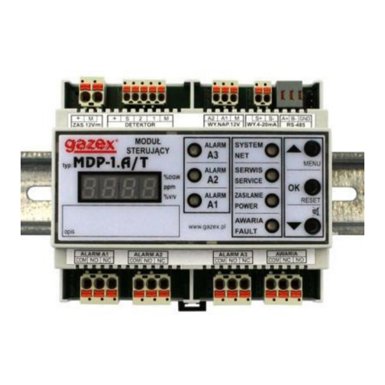
MDP-1.A/T Control Unit User Manual
Control
Unit
USER MANUAL
Issue 4W32en
PRODUCER:
Work and live SAFER with us !
issue 4W32en
M
D
P
M
D
P
[ series W3 ]
p.
2
4
4
6
9
13
15
16
16
©gazex'2016 v1609
-
1
.
A
/
-
1
.
A
/
GAZEX company.
©gazex
Page 1 / 16
T
T
Advertisement

Related Manuals for gazex MDP-1.A/ T


Summary of Contents for gazex MDP-1.A/ T
- Page 1 PRODUCER: ©gazex 2016. All rights reserved. No part of these pages, either text or image may be copied or distributed without GAZEX’s permission. The gazex logo and name as well as dex, ASBIG, “Aktywny System Bezpieczeństwa Instalacji Gazowej” are registered trademarks of the GAZEX company.
- Page 2 1. PURPOSE The MDP-1.A/T digital measurement module is designed for use with one of GAZEX gas detector types DEX/F, DEX/A or DEX/P (for operation in explosive gas atmospheres of temperature class T4) or type DG/F, DG/P or DG.EN (for operation outside potentially explosive atmospheres) - see Compatibility Table 1.2.
- Page 3 DG-PnE/N, DG-PnR DG/P DG-nn, DG-nn/N, DG-nE/N ,DG-nR DG/F DG-nn.EN DG.EN Symbols: = gas code number, = recommended cooperation (full functionality of the set) – = cooperation not permitted MDP-1.A/T Control Unit User Manual issue 4W32en Page 3 / 16 ©gazex’2016 v1609...
-
Page 4: Technical Specifications
106 x 90 x 65 mm, width x height x depth (width of 6 mod.); ca. 0,2kg Casing polystyrene, IP20; for installation in electrical switchboards on a TH35 rail MDP-1.A/T Control Unit User Manual issue 4W32en Page 4 / 16 ©gazex’2016 v1609... -
Page 5: Wiring Diagram
24 23 22 21 20 19 18 17 16 27 26 25 24 23 22 21 20 19 18 17 16 230VAC Relay Outputs No.1 Relay Outputs No.2 MDP-1.A/T Control Unit User Manual issue 4W32en Page 5 / 16 ©gazex’2016 v1609... - Page 6 4.1 Mount the module in the switchboard box, on a 35mm rail, outside an explosive area, in a place free from strong electromagnetic interference, vibrations, strokes. Caution!!! The setup can be carried out only when the power supply is off!!! MDP-1.A/T Control Unit User Manual issue 4W32en Page 6 / 16 ©gazex’2016 v1609...
- Page 7 Caution : incorrect cable polarity may result in an inability to start up the entire network of digital bus devices. MDP-1.A/T Control Unit User Manual issue 4W32en Page 7 / 16 ©gazex’2016 v1609...
- Page 8 Connect the "E" cable of the 12V= power supply from the PS... power supply unit (with battery connected); keep proper polarity (the module is protected against reverse polarity). Positive terminal "+" [1], negative terminal "M" [2]. MDP-1.A/T Control Unit User Manual issue 4W32en Page 8 / 16 ©gazex’2016 v1609...
- Page 9 (this information may be required when contacting the GAZEX service department). During this time, the module settings are initialised. 5.3 After the test phase, the module enters the sensor warm-up mode, signalling on the LED display the time left until the end of this phase.
- Page 10 A1 and A2, where A1 <= A2. The A3 alarm is only activated if the gas concentration value exceeds the A3 value (excess only). MDP-1.A/T Control Unit User Manual issue 4W32en Page 10 / 16 ©gazex’2016 v1609...
- Page 11 [ t.A3 ] – A3 alarm maintenance mode with turning off the detector power supply, [ t. n ] – auto-zeroing mode without alarm memory, [ t.SEr. ] – service mode with 1-hour long blockade of the module outputs. MDP-1.A/T Control Unit User Manual issue 4W32en Page 11 / 16 ©gazex’2016 v1609...
- Page 12 The new password should be remembered and stored in a safe place. Losing the password makes it impossible to make configuration changes to the module. Unlocking the password is possible only by GAZEX (paid service). [ tESt ] 5.5.6...
- Page 13 - alarm output active Pulsating light - the output was active, currently inactive, off - the output was and is inactive. c) Green NET light signals RS485 communication status: MDP-1.A/T Control Unit User Manual issue 4W32en Page 13 / 16 ©gazex’2016 v1609...
- Page 14 In the case of a measuring detector, check that the displayed measured gas concentration value matches the test gas concentration (the measurement accuracy of MDP-1.A/T Control Unit User Manual issue 4W32en Page 14 / 16 ©gazex’2016 v1609...
- Page 15 If you notice effects other then the above mentioned contact an Authorised Service or the Producer. MDP-1.A/T Control Unit User Manual issue 4W32en Page 15 / 16 ©gazex’2016 v1609...
-
Page 16: Maintenance / Operation
Customers to date, GAZEX reserves the right to make minor changes to the technical specifications of the products supplied and not included in this User Manual, and to change its content.
Need help?
Do you have a question about the MDP-1.A/ T and is the answer not in the manual?
Questions and answers