Advertisement
Quick Links
Warszawa
Read carefully this entire manual BEFORE
installation.
The installation can be started after the
content of this manual has been fully
understood.
Follow the recommendations and
warnings provided in this manual
to maintain safety when installing
and operating the unit.
Keep the manual as reference for the User
of the Two-Threshold Gas Detection System.
1.
Application and compatibility table
2.
Specifications
Description and connection of MD in the system
3.
4.
Installation of MD
PROBLEM? Helpful tips
5.
Maintenance / operation
Periodical Inspection Protocol
PRODUCER:
©gazex '2011 All right reserved. Reproducing and copying of this manual in whole or part without consent of GAZEX is prohibited.
Logo of gazex, name of gazex, dex, ASBIG, Active Safety System of Gas System are reserved trademarks of GAZEX
MD-2(4).( A ) Control Unit, User's Manual edition 2U3en
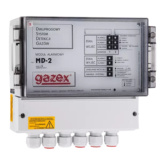
Control Unit
USER'S
MANUAL
PRODUCER:
Logo of TÜV CERT EN ISO 9001 is a reserved trademark of TÜV Rheinland Euroqua.
Work and live SAFER with us!!!
MD-2
MD-2.A
type
MD-4
MD-4.A
edition 2U3en
page 2
gazex'2011 v1108
series U3
3
4
7
10
10
12
©gazex
Page 1 /14
Advertisement

Subscribe to Our Youtube Channel
Related Manuals for gazex MD-2


Summary of Contents for gazex MD-2
- Page 1 PRODUCER: ©gazex ’2011 All right reserved. Reproducing and copying of this manual in whole or part without consent of GAZEX is prohibited. Logo of gazex, name of gazex, dex, ASBIG, Active Safety System of Gas System are reserved trademarks of GAZEX Logo of TÜV CERT EN ISO 9001 is a reserved trademark of TÜV Rheinland Euroqua.
- Page 2 (described in Section 4.2 of this manual) are reduced by 50%. The unit can control operation of one or two (MD-2, MD-2.A) or up to four (MD-4, MD-4.A) two-threshold DEX and/or DG detectors (various detector types can be used at a time).
-
Page 3: Specifications
2. SPECIFICATIONS MD-2, MD-4 - 230V AC, 50Hz (allowed voltage fluctuations: +10%,-14%) Supply voltage MD-2.A, MD-4.A - 12V DC ( allowed: 10.5V ÷ 13.8V=) Power consumption max. 15W (MD-...A : max 12W) +5C to 35C recommended optimal, -10C to +40C allowed constantly, Operating temperature -15... - Page 4 ACCUMULATOR 7Ah or 17Ah 15 16 17 18 M + M + WYJ. NAP.12V UNIT No. n 12V DC power supply connection Cascade connection of units MD-2(4).( A ) Control Unit, User’s Manual edition 2U3en Page 4 /14 gazex’2011 v1108...
- Page 5 (SILENCE) BEZ PAM. optical memory of alarm states active memory memory off at outputs and inputs MEMORY) MD-2(4).( A ) Control Unit, User’s Manual edition 2U3en Page 5 /14 gazex’2011 v1108...
- Page 6 Meaning of lamp statuses: 0 = off, 1 = on , 1/0 = slowly blinking, x = any state (resulting from system configuration or previous states). MD-2(4).( A ) Control Unit, User’s Manual edition 2U3en Page 6 /14 gazex’2011 v1108...
- Page 7 DEX detectors are to be installed activate power supply circuits with W1 microswitches „WYŁĄCZ” („DEACTIVATE”) on the terminal board (with number corresponding to the number of the detector MD-2(4).( A ) Control Unit, User’s Manual edition 2U3en Page 7 /14...
- Page 8 (without cable glands) or through the seal of the terminal compartment cover. 4.5. For MD-2(4) connect 230V AC power supply „B” cable. The module is equipped with internal, 1-pole power switch. MD requires no earthing and has no protection terminal.
- Page 9 - tightly close the transparent unit cover. - It is recommended to put a seal on the unit covers (to limit the access to the MD by unauthorized persons). MD-2(4).( A ) Control Unit, User’s Manual edition 2U3en Page 9 /14 gazex’2011 v1108...
- Page 10 (with identical, slow blow fuse), carry out the replacement with power shut off When effects other than those described above are observed contact the Authorized Distributor or Manufacturer. MD-2(4).( A ) Control Unit, User’s Manual edition 2U3en Page 10 /14 gazex’2011 v1108...
-
Page 11: Maintenance / Operation
Customers, GAZEX reserves the right to introduce minor changes in specifications of the products supplied and not indicated in this Manual and to change the content of this Manual. - Page 12 System ( type ) ( calibration ) ( location ) (fill in the table before System installation!) The protocol includes five numbered sheets with gazex logo on the reverse side. DETECTOR / SYSTEM START-UP: Remarks Remarks DATE Time...
- Page 13 RESPONSE Inspection Time DETECTOR OTHER symptoms Actions taken Legible signature of the DATE No. / state (valve condition) inspector (full name) MD-2(4).( A ) Control Unit, User’s Manual edition 2U3en Page 13 /14 gazex’2011 v1108...
- Page 14 MD-2(4).( A ) Control Unit, User’s Manual edition 2U3en Page 14 /14 gazex’2011 v1108...
Need help?
Do you have a question about the MD-2 and is the answer not in the manual?
Questions and answers