Table of Contents
Advertisement
Quick Links
INSTALLATION, OPERATION & APPLICATION GUIDE
For more information on our complete range of American-made products – plus wiring diagrams, troubleshooting tips and more, visit us at www.icmcontrols.com
SPECIFICATIONS
Input:
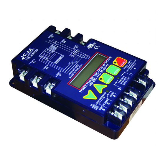
• Line voltage: Universal, 190-600 VAC
• Frequency: 50-60 Hz
• Control voltage: 18-240 VAC
• Load side monitoring: Optional
Output:
• Type: Relay, SPDT
• Voltage range: 277 VAC @ 6A, general
purpose
Ambient Operating Temperature: -40ºF
to +167ºF (-40ºC to +75ºC)
Storage Temperature: -40ºF to +185ºF
(-40ºC to +80ºC)
Line Voltage: Universal 190-600 VAC
Phase Unbalance Protection : 2-20%
adjustable
Over/Under Voltage Protection:
• Under Voltage: 2-25% adjustable
• Over Voltage: 2-25% adjustable
Phase Loss Protection: Equals 25% of
nominal for any given phase; system
will shut down and a fault will be
recorded should this occur
Delay on Break Timer: 0 to 10 minutes
adjustable
Control Voltage: 18-240 VAC
Control Mode: ON/OFF
CAUTION!
Installation of the ICM450A and ICM450A PLUS+ shall be performed by trained
technicians only. Adhere to all local and national electric codes.
Disconnect all power to the system before making any connections.
INSTALLATION
1. Using (2) #8 screws, mount the ICM450A and ICM450A PLUS+ in a cool, dry,
easily accessible location in the control panel.
2. Connect voltage as shown in Figure 1 (below). Leave existing line and load side
connections intact on the contactor.
3. Load side monitoring is optional (unit may be used to monitor line side only).
Wire the contactor and optional control voltage monitoring as in Figure 2.
Note: Load/line wire must be rated for the voltage applied. Do not use wire
smaller than 20 AWG.
4. Upon application of power, the ICM450A and ICM450A PLUS+ will be on line and
will begin to monitor the system.
Figure 1
LOAD
T3
Incoming 3-phase
voltage from load
T2
or "back" side of
contactor (optional)
T1
* User may install 1 AMP inline fuses rated at the applied input voltage to the line
side connections.
• Terminals 4 and 5 are the control signal input terminals
• "Control Mode" is turned ON or OFF in setup
ICM450A & ICM450A PLUS
Mechanical:
• Mounting: Surface mount using (2)
#8 screws
• Terminations: 1/4" quick connects
• Weight: 12 ounces (341 grams)
ModBus:
• RS485 Communication
(ICM 450A PLUS+)
• Node ID: 17
• Baud rate: 9600
• Stop Bits: 2
• Parity: none
• Data Bits: 8
** NOTE: These Settings cannot be
changed.
Dimensions: 6.5"L x 4.75"W x 1.09"D
Fault Interrogation Delay:
• Time Delay: 0 to 15 seconds
adjustable
• Provides a delay between fault
detection and system shutdown -
helps to eliminate nuisance trips or
unnecessary shutdowns
Reset Mode: 0 (auto) or 1-10 retries
Set Date and Time: Provides real
time clock for date and time stamp
(ICM450A PLUS+)
Language: Set to English or Spanish
language for display
LINE
Incoming 3-phase voltage from
L3
line or "front" side of contactor
L2
The incoming 3-phase voltage is
used to power up the ICM450A
L1
as well (190-600)
INSTALLATION
• With "Control Mode" set to "ON," there must be a voltage present on terminals 4
and 5 for the relay output terminals 1 and 2 to close; this voltage can be supplied
from a thermostat, pressure switch, etc.
• When the voltage on these terminals is re-applied, the unit will not re-energize
until the delay on break (0-10 minutes) time has elapsed
• Use of terminals 4 and 5 is optional; they will be ignored if the "Control Mode" is
set to "OFF"
• Terminals 1 and 2 are "dry," normally open contacts
• Terminals 1 and 2 are closed when power is within specifications
• Terminals 1 and 2 open when there is a
fault condition
• Terminals 1 and 2 open when there is a loss
E53944
of the control signal with "Control Mode"
set to "ON"
Note 1: Terminals 6, 7 and 8 used for
ModBus communication on
ICM450A PLUS+.
Note 2: Use of female quick connect terminals
suitable for field wiring required.
Female quick-connect terminals
suitable for factory-wiring only are not permitted.
MODBUS DATA MAPPING QR CODE
To Access the MODBUS data mapping tables,
SCAN the QR Bar code to the right.
DIN RAIL MOUNTING INSTRUCTIONS
1. Align the DIN rail mounting plate with the 4 holes on the
back side of the ICM450A/450A Plus+.
2. Thread the four # 10 screws provided in the kit through
the ICM450A/450A Plus+ mounting holes from the top
side and thread into the mounting plate as seen in fig 5.
** Optional din rail mounting kit sold separately
(Order: DIN-ICM450A)
ICM450A AND ICM450A PLUS+ WIRING DIAGRAMS
2-Pole Contactor
Load
3
LOAD
T3
T2
T1
1
2
3
Load 1
Load 2
SETTING THE PARAMETERS
1. Press the SETUP button to enter Setup mode. Setup LED will light.
2. Use the
and
3. Scroll through setup by pressing and releasing the SETUP button.
4. When the last parameter has been set, the phase average will be displayed and
the Setup LED will automatically turn OFF.
TERMINATING THE RESISTOR
The ICM450A PLUS+ is equipped with an internal terminator resistor which can be
enabled or disabled in the set up.
BUTTON FUNCTIONS
Press arrows to scroll through
and select user parameter
settings in Setup mode. HOLD
down for fast edit.
Voltage Read Calibration
Hold down both the UP & Down buttons simultaneously to enter calibration
mode (Fault and Setup LEDs will flash). Press the Up & Down buttons individually
to adjust display voltage allowing a few seconds between presses for voltage
averaging. Press SETUP to exit calibration
Programmable 3-Phase Line Voltage Monitors
(CONTINUED)
Figure 2
Contactor
Coil
3-Pole Contactor
L1 L2
L3
LINE
LOAD
L3
T3
L2
T2
L1
T1
SETUP
READ
FAULT
4
5
6
7
8
1
Optional Control
Voltage
18-240 VAC
Load 1
Load 2
Load 3
LOAD
arrows to change user parameters.
Press to enter
Hold for voltage
Setup mode
display a
and select user
b
parameters.
(simultaneously).
+
COM NO NC
Contactor Voltage
(18-240 VAC)
Optional Control Voltage
L1 L2
L3
LINE
L3
L2
L1
SETUP
READ
FAULT
2
3
4
5
6
7
8
Optional Control
Voltage
18-240 VAC
LOAD
Press to read faults.
b,
Hold for 5 seconds
c, a
c
to clear faults and
reset memory.
Advertisement
Table of Contents

Related Manuals for ICM Controls ICM450A


Summary of Contents for ICM Controls ICM450A
- Page 1 LOAD INSTALLATION SETTING THE PARAMETERS 1. Using (2) #8 screws, mount the ICM450A and ICM450A PLUS+ in a cool, dry, 1. Press the SETUP button to enter Setup mode. Setup LED will light. easily accessible location in the control panel.
- Page 2 Loads 1, 2, or 3 are not in sequence Back Phase Rev 2. Swap any 2 phases on the load side of the ICM450A and ICM450A PLUS+ only (example: swap load 1 and load 2) * (not 120º phase shifted) 3.
Need help?
Do you have a question about the ICM450A and is the answer not in the manual?
Questions and answers
Do any of your units record information in the cloud, and for how long is it accessible. We are interested in such a unit for information as opposed to triggering a relay which would remove a motor from service.