ICM Controls ICM450 Application Manual
Three phase voltage monitors, programmable, 25-fault memory
Hide thumbs
Also See for ICM450:
Advertisement
Advertisement
Table of Contents

Related Manuals for ICM Controls ICM450


Summary of Contents for ICM Controls ICM450
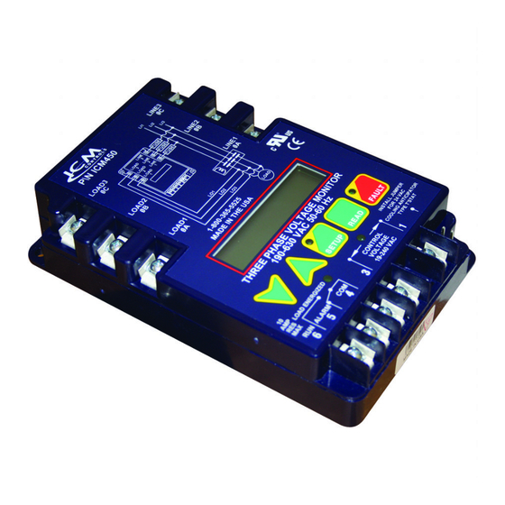
- Page 1 ICM450 Three Phase Voltage Monitors Programmable, 25-Fault Memory Portects motors from premature failure and burnouts Application Guide For information on our complete range of American-made products — plus wiring diagrams, troubleshooting tips and more, visit us at www.icmcontrols.com...
-
Page 2: Specifications
• Provides a delay between fault detection and system shutdown - helps to eliminate nuisance trips or unnecessary shutdowns Caution Installation of the ICM450 shall be performed by trained technicians only. Adhere to all local and national electric codes. Disconnect all power to the system before making any connections. -
Page 3: Installation
Installation 1. Using (2) #8 screws, mount the ICM450 in a cool, dry, easily accessible location in the control panel. 2. Connect voltage as shown in Figure 1 (below). Leave existing line and load side connections intact on the contactor. -
Page 4: Wiring Diagrams
Wiring Diagrams 2-Pole Contactor 3-Pole Contactor Fuse Fuse Fuse Fuse Fuse Fuse Control Control Voltage Voltage * Thermostat pressure switch, etc. * Thermostat pressure switch, etc. L0AD L0AD Setting the Parameters 1. Press the green SETUP button to enter Setup mode. Setup LED will light. 2. - Page 5 1 and 3 of the ICM450 * Non-critical faults are faults such as High/Low Voltage and Phase Unbalance. Critical faults, such as Phase Loss and Phase Reversal, have a fault interrogation of under 2 seconds and it is not user adjustable.
- Page 6 Fault Conditions Press and release fault button to scroll through all saved faults. Note: For initial setup, press and hold FAULT for 5 seconds to remove any previously stored faults. Fault Problem Corrective Action Back Phase Not all three of the phases 1.
-
Page 7: Led Status
Troubleshooting Problem LED Status Corrective Action Readout Load will not Phase All LEDs Off Confirm that the control input is properly energize Avg. connected and configured Load will not Phase Load LED Off, Press FAULT to observe the current fault; energize Avg. - Page 8 ONE-YEAR LIMITED WARRANTY The Seller warrants its products against defects in material or workmanship for a period of one (1) year from the date of manufacture. The liability of the Seller is limited, at its option, to repair, replace or issue a non-case credit for the purchase prices of the goods which are provided to be defective.
- Page 9 ATTENTION TECHNICIANS DO NOT USE THE FACTORY PRESETS ON THIS MONITOR CHANGE SETTINGS TO THE ONES LISTED BELOW Description Setting Voltage Imbalance Delay on break 10 minutes Restart Set to “0” The monitor will act as a manual reset auto-reset defeats the purpose...
Need help?
Do you have a question about the ICM450 and is the answer not in the manual?
Questions and answers