Table of Contents
Advertisement
Quick Links
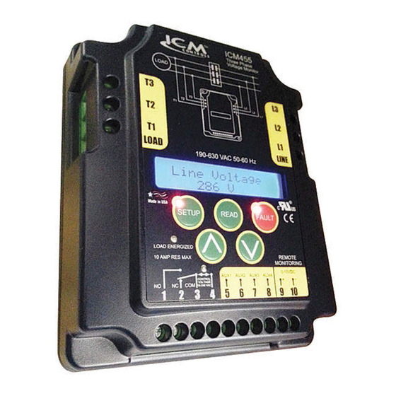
ICM455
Programmable,
Three-Phase
Voltage Monitor
Important Safety Information
HIGH VOLTAGE WARNING! – Turn off power at the
main service panel before installing.
Specifications
Input
• Line Voltage: 190 – 630 VAC
• Frequency: 50 – 60 Hz
• Load Side Monitoring: Optional
• Control Voltage: 18 – 240 VAC
Control Operating Temperature
• Operating Temperature: -40°F to 167°F (-40°C to 75°C)
• Storage Temperature: -40°F to 185°F (-40°C to 80°C)
LCD Operating Temperature
• Operating Temperature: -4°F to 167°F (-40°C to 75°C)
Mechanical
• Mounting: Surface mount using two (2) #8 screws
• Terminations: Screw terminals
• Dimensions: 5.5"L x 4.5"W x 1.5"H
Phase Unbalance Protection
• Voltage Unbalance: 2-20%, adjustable
Over/Under Voltage
• Under Voltage: 2-25%, adjustable
• Over Voltage: 2-25%, adjustable
Phase Loss Protection
• Phase Loss Condition: Equals 25% of nominal for any given phase; system will
shut down and a fault will be recorded if this should occur.
Delay on Break Timer
• Control Voltage: 18-240 VAC
• Time Delay: 15 seconds to 10 minutes
Fault Interrogation Delay
• Time Delay: 0 – 15 seconds, adjustable
• Provides a delay between fault detection and system shutdown—helps to eliminate
nuisance trips and unnecessary shutdowns.
Installation
1. Turn off power at main service panel.
2. Using two (2) #8 screws, mount the ICM455 in a cool, dry, easily accessible
location in the control panel.
3. Connect voltage as shown in "Wiring Diagram". Leave existing line and load side
connections intact on the contactor.
4. Load side monitoring is optional (unit may be used to monitor line side only). Wire
the contactor and optional control voltage monitor as shown in "System Diagram".
Note: Load/line wire must be rated for 3-phase voltage rating, 20ga minimum.
5. Upon application of power, the ICM455 will be on line and will begin to monitor
the system.
Note: If voltage is not correct, see "Voltage Read Calibration" in Button
Functions section
• Terminals 3 and 4 are the control signal input terminals.
• "Control Mode" is turned ON or OFF in setup.
• With "Control Mode" set to ON, there must be a voltage present on terminals 3
and 4 for the relay output terminals 1 and 3 to close; this voltage can be supplied
from a thermostat, pressure switch, etc.
• When the voltage on theses terminals is re-applied, the unit will not re-energize
until the delay on break (0-10 minutes) time has elapsed.
• Use of terminals 3 and 4 is optional; they will be ignored if the "Control Mode" is
switched to OFF.
• Terminals 1 and 3 are "dry", normally open contacts.
• Terminals 1 and 3 are closed when power is within specifications.
• Terminals 1 and 3 open when there is a fault condition.
• Terminals 1 and 3 open when there is a loss of the control signal with "Control
Mode" set to ON.
• Auxiliary terminals will be used in future models.
Output
• Type: Relay, SPDT
• Voltage Range: 240 VAC at 10A max
• Frequency: 50 – 60 Hz
• Remote Monitor Voltage: 0 – 10 VDC
Wiring Diagram
Typical System Diagram
CONTROL
VOLTAGE
NO
COM
NC
18-240 VAC
Control
Voltage
Load
Contactor
Setting the Parameters
1. Press the green SETUP button to enter the setup mode. Setup LED will light.
2. Use the
and
buttons to change user parameters.
3. Scroll through setup by pressing and releasing the SETUP button.
4. When the last parameter has been set, the phase average will be displayed and
the setup LED will automatically turn off.
Button Functions
Press arrow to scroll through and select parameter settings in Setup
Mode.
Voltage Read Calibration:
Hold both down to calibrate line voltage. Fault and setup LEDs will flash.
buttons to adjust. Press SETUP to exit calibration.
Use the
and
Press to enter Setup Mode and select user parameters. Setup LED
illuminates when in Setup Mode.
Press to return to home screen, which alternates between line voltage
and phase average.
Press to read faults. Hold for 5 seconds to clear faults and reset memory.
Fault light will blink when fault has been added to memory.
Press and hold to reset system due to system error – this will not reset
the parameters.
To turn backlight on, press any button.
Output Conditions
Output Voltage
8 VDC
7 VDC
6 VDC
5 VDC
4 VDC
2 VDC
0 VDC
Contactor
REMOTE
MONITORING
0-10VDC
AUX1 AUX2 AUX3 AUX4
+
Thermostat
or Pressure
Switch
Condition
Phase Loss
Phase Reversal
Under Voltage
Over Voltage
Phase Imbalance
Load Energized
No Power to Unit
-
Advertisement
Table of Contents

Subscribe to Our Youtube Channel
Related Manuals for ICM Controls ICM455


Summary of Contents for ICM Controls ICM455
- Page 1 • Time Delay: 0 – 15 seconds, adjustable • Provides a delay between fault detection and system shutdown—helps to eliminate Press to read faults. Hold for 5 seconds to clear faults and reset memory. nuisance trips and unnecessary shutdowns. Fault light will blink when fault has been added to memory. Press and hold to reset system due to system error – this will not reset Installation the parameters. 1. Turn off power at main service panel. To turn backlight on, press any button. 2. Using two (2) #8 screws, mount the ICM455 in a cool, dry, easily accessible location in the control panel. 3. Connect voltage as shown in “Wiring Diagram”. Leave existing line and load side Output Conditions connections intact on the contactor. 4. Load side monitoring is optional (unit may be used to monitor line side only). Wire Output Voltage Condition the contactor and optional control voltage monitor as shown in “System Diagram”. 8 VDC Phase Loss Note: Load/line wire must be rated for 3-phase voltage rating, 20ga minimum.
- Page 2 2. Increase the percentage under-voltage setting if necessary. 3. Increase fault time interrogation if necessary. Load Not all three of the phases on the load side are present 1. Re-energize the contactor. Phase 2. If the fault reappears after the load energizes: Loss a. Turn all power OFF. b. Check all load side connections. c. Check the contacts of the contactor for damage, debris, or excess carbon. Load Loads 1, 2, or 3 are not in sequence (not 120° Phase 1. Turn OFF all power. Phase Rev Shifted) 2. Swap any 2 phases on the load side of the ICM455 only (example: swap load 1 and 2).* 3. Re-apply power. Load A voltage unbalance between the three load phases 1. Press the READ button to observe the present load voltages. Check system for unbalance cause. Phase exceeds the unbalance set point 2. Increase the fault interrogation time if necessary. Unbalance 3. Increase the percent unbalance setting if necessary. Brownout All three phases lost (0V) Check system supply voltage for cause of voltage loss * ONLY swap phases during initial setup, not after the ICM455 has been in operation without errors. Troubleshooting Parameter LCD Readout LED Status...
Need help?
Do you have a question about the ICM455 and is the answer not in the manual?
Questions and answers