Table of Contents
Advertisement
Quick Links
Advertisement
Table of Contents

Related Manuals for TELEDYNE OLDHAM SIMTRONICS MX 43


Summary of Contents for TELEDYNE OLDHAM SIMTRONICS MX 43
- Page 1 SER GUIDE MX 43 ANALOG AND DIGITAL CONTROLLER NPM43EN Revision K.0...
- Page 2 Copyright March 2020 by TELEDYNE OLDHAM SIMTRONICS S.A.S. All rights reserved. The reproduction of all or any section of this document in any form whatsoever without the written permission of TELEDYNE OLDHAM SIMTRONICS S.A.S. is forbidden. The information contained in this manual is accurate to our knowledge.
-
Page 3: Table Of Contents
Important Information ..................2 Liability Limits ....................... 2 Warranty ........................ 3 General Introduction ..............5 Purpose of the MX 43 controller ..............5 The MX 43 Controller ..................6 The COM 43 Application ................7 Firmplate ....................... 8 Mechanical Installation ..............9 MX 43 Controller .................... - Page 4 Cleaning ....................... 61 Fuse replacement ..................... 61 10 Certificate of Compliance ............63 11 Technical Specifications ............... 69 MX 43 Controller ....................69 Relay Module ...................... 71 16-Logic Input Module ..................72 8-Analog Input Module ................... 72 4-Analog Output Module ................73 12 RS485 Digital Output ...............
- Page 5 Connecting detectors other than TELEDYNE OLDHAM SIMTRONICS detectors to the MX 43 controller ........... 84 14 MX 43 in cabinets ................87 Presentation ......................87 Codification ......................88 Electrical connections ..................91 Control panel fixing ..................94 Internal implantation ..................97 Technical specifications .................
- Page 6 MX 43 ANALOG AND DIGITAL CONTROLLER USER GUIDE NPM43EN Revision K.0...
-
Page 7: General Information
MX 43 ANALOG AND DIGITAL CONTROLLER USER GUIDE 1 General Information User Manual The instructions given in this manual must be read thoroughly before installation and start-up, particularly those concerning the points related to the safety of the end-user. This user manual must be made available to every person involved in the activation, use, maintenance, and repair of the unit. -
Page 8: Safety Instructions
TELEDYNE OLDHAM SIMTRONICS Neither nor any other associated company under any circumstances can be held liable for any damage, including, without limitations, damages for loss or interruption of manufacture, loss of information, defect of the MX 43 controller, injuries, NPM43EN Revision K.0... -
Page 9: Warranty
MX 43 ANALOG AND DIGITAL CONTROLLER USER GUIDE loss of time, financial or material loss, or any direct or indirect consequence of loss occurring in TELEDYNE the context of the use or impossibility of use of the product, even in the event that OLDHAM SIMTRONICS has been informed of such damage. - Page 10 MX 43 ANALOG AND DIGITAL CONTROLLER USER GUIDE NPM43EN Revision K.0...
-
Page 11: General Introduction
■ relay outputs, and analog outputs). The MX 43 instantly handles the measurements of detectors and input modules. As soon as the measurements reach the programmed limit, a sound and visual alarm are given. At the same time, the corresponding relay or relays are activated, in turn controlling the additional internal or external actions envisaged by the user. -
Page 12: The Mx 43 Controller
4 * 4-20 mA outputs detectors 8 analog inputs Analog recorders Figure 2: Example of an MX 43 configuration using different analog and digital detectors as well as digital modules. The MX 43 Controller 2.2.1 Versions The MX 43 controller is available in several versions: Wall-mounted version 4 lines. -
Page 13: The Com 43 Application
ANALOG AND DIGITAL CONTROLLER USER GUIDE Figure 3: Wall-mounted version MX 43 (left illustration) or rack- mounted version (right illustration). The following table details the different configurations that are possible, depending on the type of unit. On each line, it is possible to connect a 4-20mA analog detector or one, or several, digitally addressable modules. -
Page 14: Firmplate
MX 43 ANALOG AND DIGITAL CONTROLLER USER GUIDE Firmplate Example: It contains relevant information with respect to the controller version (CSA or ATEX variants). Tag. Description All models: Name and address of the Manufacturer Product name CE marking with identification of the Notified Body that assessed the TELEDYNE OLDHAM SIMTRONICS manufacturing quality system (0080 –... -
Page 15: Mechanical Installation
Attachment of the wall enclosure Access to the controller must be ensured in the front in order to facilitate adjustments, monitoring, and cabling. A space of 400 mm is necessary in front of the MX 43 for opening the door. - Page 16 This rack is built into a bay or a standard 19” cabinet. You should leave ½ U (22 mm) of space above and below the rack so as to assure the proper ventilation of the MX 43. Figure 6: Size of the rack-mounted version.
-
Page 17: Digital Modules
MX 43 ANALOG AND DIGITAL CONTROLLER USER GUIDE Digital Modules Wiring and Electrical Connections The cabling is the subject of the paragraph page 37. 3.2.1 Gas detectors Refer to the manual supplied with each detector. Location Each detector shall be positioned at ground level, on the ceiling, at the height of the respiratory tract, or near air extraction ducts, depending on the density of the gas to be detected or applied. - Page 18 MX 43 ANALOG AND DIGITAL CONTROLLER USER GUIDE NPM43EN Revision K.0...
-
Page 19: The Mx 43 Controller
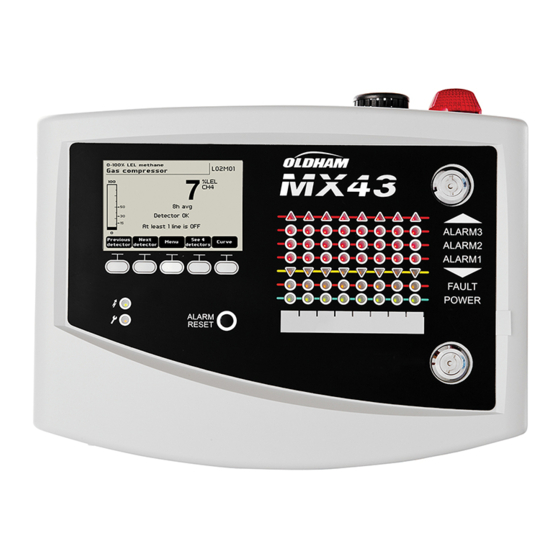
MX 43 ANALOG AND DIGITAL CONTROLLER USER GUIDE 4 The MX 43 Controller The versions in cabinet have differences in the arrangement of the components. See specific chapter 14 after reading this notice in its entirety. Overview of the Unit 4.1.1... - Page 20 MX 43 ANALOG AND DIGITAL CONTROLLER USER GUIDE 4.1.2 Internal view Figure 9: Internal view of the wall-mounted version (top) and rack- mounted version (bottom). Rep. Function LED digital communication status indicators. The information displayed by each red-green diode pair...
- Page 21 MX 43 ANALOG AND DIGITAL CONTROLLER USER GUIDE Rep. Function Connector for the direct current external supply. Battery fuse (4A) and external power supply (21 to 28 VDC, 3.2 to 4 A max.). Connector for - Main entry Power Supply 24VDC - Internal siren 24 VDC –...
- Page 22 Once the unit configuration or update is complete, always set the selector in the "0" position. CR2032 lithium battery. Safeguards the preservation of the records and real time clock in case of total power failure. Autonomy of approx. 450 days with the power off. At each battery change, power the MX 43. Microcontroller PCB.
-
Page 23: Front Plate
MX 43 ANALOG AND DIGITAL CONTROLLER USER GUIDE Optional USB key. Allows you to save MX 43 input (measurements, alarms, etc.) or to transfer files from the USB key to the MX 43 MX 43 (transferring configuration or updates to the 's onboard software). - Page 24 Zone Status Indicators (C) Eight bars of 7 indicators each are displayed on the controller. The 4 bars to the right are not operative on a 4-line MX 43. Each bar represents a geographic area of the complete installation and not the 4 or 8 lines of the MX 43.
- Page 25 Located in the upper portion of the box, the flash is optionally available solely in the wall- mounted version. It is configured via the COM 43 application. 4.2.5 Status indicators (F and G) These two indicators reflect the status of the MX 43. Icon Function Green general start/stop indicator denoting the power supply status - Fixed: Correct power supply.
-
Page 26: Alarm And Relay Thresholds
MX 43 ANALOG AND DIGITAL CONTROLLER USER GUIDE Figure 13: Pulling the tab. Alarm and Relay Thresholds Alarm thresholds, relay programming, the management of time delays, and methods of release are controlled over the COM 43 application. Programming MX 43. - Page 27 MX 43 ANALOG AND DIGITAL CONTROLLER USER GUIDE Event Message screen Alarm relay Alarm Relay LED alarm Internal buzzer (normal) (buzzer) Appearance AL (1,2,3) and Activated Activated Fixed light: Activated inverse video of the detector alarm reset Press AL (1,2,3) and...
-
Page 28: Usb Key Operation
0 to 9 and special characters $ % ‘ - _ @ ~ ` ! ( ) { } ^ # & may be used. If other characters are added, the MX 43 will not be able to read the file. - Page 29 0. The will then restart using the new uploaded application. 4.4.3 Using the MX 43 input files on a PC Ejecting the USB key Never remove the USB without following the procedure below: You could lose all of the data on the USB key, and your files will not be transferred.
- Page 30 MX 43 ANALOG AND DIGITAL CONTROLLER USER GUIDE Detector name Last sensor replacement Lines contain information about the configuration ■ of the first sensor. The following blocks contain information about each of the individual MX 43 sensors connected to the Further down, there is a table grouped together.
-
Page 31: Digital Modules
Addressable Digital Modules These modules are connected on each of the available 4 or 8 lines of the MX 43, up to a limit of 32 modules on a version of 8-lines or 16 modules on a 4-line version. The following table... -
Page 32: Rs485 Transmission
The cable shielding must be connected to the grounding rod of the MX 43. At the end of the busbar, the 120-Ohm end of line resistor ( ) must be EOL RESISTOR/RESISTANCE F.D.L... -
Page 33: Configuration Of Communication
MX 43 ANALOG AND DIGITAL CONTROLLER USER GUIDE Configuration of Communication 5.3.1 Module Address All the digital modules on a line must be identified by a unique address. Switches 1 to 5 of the configuration block of each module make it possible to establish an address number (1 to 32) in binary mode. -
Page 34: Relay Modules
MX 43 ANALOG AND DIGITAL CONTROLLER USER GUIDE 5.3.2 End of line Resistor Solely for the last module of each line, switch no.8 ) to ON or set EOL RESISTOR/RESISTANCE F.D.L. the jumper of the analog input PCB to Closed Figure 18: End of line resistor switch in position “ON”. - Page 35 For the 4-relay module, only switches 1 to 4 are active. E – Programmable relays In its maximum configuration, the MX 43 can manage 24 external relays (or 24 modules with 1 stated relay or 3 modules of 8, all stated relays). The relays are individually programmable. The operation of each relay depends on its configuration.
-
Page 36: 16-Logic Input Module
5.5.1 Function This digital module allows the monitoring of 1 to 16 logic inputs by the MX 43. In the 8-line version, the controller can manage a maximum of 32 logic inputs distributed, for example, either on 32 logic input modules with one input... - Page 37 C –Logic input connectors Each of these 16 inputs can be connected to a voltage-free contact as per Figure 39. Input status is transmitted by the digital line to the MX 43. There is no alarm when the contact is closed.
-
Page 38: 8-Analog Input Module
MX 43 ANALOG AND DIGITAL CONTROLLER USER GUIDE 8-Analog Input Module 5.6.1 Function This digital module enables the monitoring of 8 analog (4-20 mA or Wheatstone bridge) inputs. Digital line 8 analog inputs 4 wires Figure 23: 8-analog inputs. 5.6.2 Introduction Ref.. - Page 39 MX 43 ANALOG AND DIGITAL CONTROLLER USER GUIDE 5.6.3 Connection Refer to chapter 6, on page 37. 5.6.4 Configuration Configured via the COM 43 application. Note related to manual calibration of the detectors connected to an 8-analog input module. 1. Zero calibration Inject standard gas to obtain 4 mA.
-
Page 40: 4-Analog Output Module
A –Logic input connectors Each of these two terminal jacks (Figure 26, A) may be connected to a voltage-free contact in accordance with . Input status is transmitted by the digital line to the MX 43. C – Module configuration switches... - Page 41 MX 43 ANALOG AND DIGITAL CONTROLLER USER GUIDE Term Symbol Slave number Module Address See details in the paragraph on page 27. Numéro esclave Frame filling Factory settings. Do not modify. Remplissage de trame Delay Factory settings. Do not modify.
- Page 42 MX 43 ANALOG AND DIGITAL CONTROLLER USER GUIDE NPM43EN Revision K.0...
-
Page 43: Wiring And Electrical Connections
Concerning versions in cabinet, see the specific chapter 14. This chapter details the electrical connections of all the system components (MX 43, modules, additional equipment). Controller Connection The electrical connections must be carried out by qualified personnel in compliance with the different directives in force in the country of installation. - Page 44 External 24V DC Power Supply The MX 43 can be powered from a 22 to 28 V AC source at 50/3.2 A, 1.5 A max. In this case, connect the 24VDC source to the corresponding terminal jack (Figure 29, A) respecting polarities.
- Page 45 (110-240 VAC). The battery pack requires continuous charging for 7 days before reaching its maximum capacity. Its autonomy depends on the MX 43 configuration. If the battery pack is not installed at delivery, proceed as follows: 1. Position and fix the battery pack (A) at the place indicated using the 4 screws supplied.
- Page 46 MPI-22A, nominal impedance of 100 Ohms. 6.1.7 Analog channels For an analog 4-20mA detector connected directly on the MX 43 channels, please connect the detector as shown below. “I” is the 4-20mA signal, 0 and 24V correspond to the power supply.
- Page 47 Connect the external equipment to the control on terminal jacks R1 to R5. The relay contacts are represented when no power applies to the MX 43. The position of the contacts (no alarm) once the MX 43 is powered will depend on the relay configuration (energized or de-energized). The relays are programmed via the COM 43 application.
-
Page 48: 4- Or 8-Relay Modules
This connector, powered at 24VDC by the MX 43, allows power supply for a rotating light and a siren optionally available for the MX 43 in wall-mounted version. In the rack version, these connectors may be taken over to power a sound alarm (24VDC, 19mA max.) and a visual alarm (24... -
Page 49: 16-Logic Input Module
ANALOG AND DIGITAL CONTROLLER USER GUIDE 16-Logic Input Module Supervised contacts Supervised contact To MX 43 To next or previous module module Figure 39: 16-logic input module connections. If this module is the last on the line, do not forget to set the switch marked resistor/resistance FDL to ON. -
Page 50: 4-Analog Output Module
4-20 mA n°2 4-20 mA n°4 To the next module To MX 43 or the previous module Figure 42: 4-analog output module connections. If this module is the last of the line, do not forget to set the jumper switch marked EOL Resistor/FDL resistance to the ON position. -
Page 51: Menus
See page 47 See page 48 See page 48 ↓ ↓ ↓ 4 MAINTENANCE 5 INFORMATION 6. USB KEY See page 51 See page 52 See page 56 Figure 43: General menu tree of the MX 43. NPM43EN Revision K.0... -
Page 52: Navigation Key Functions
MX 43 ANALOG AND DIGITAL CONTROLLER USER GUIDE Navigation Key Functions Function Vertical displacement in the selected menu block. Horizontal displacement between two menu blocks. Enter Validation of the selected line. Escape Return to previous screen. Table 11: Function of the navigation keys. -
Page 53: Main Menu
Zone of indication of activated alarms with blinking threshold display. The screen changes to inverse video (Figure 44, screen on the right). Figure 45: Example of a curve display screen. Main Menu This displays all the management menus of MX 43. Figure 46: Main menu. 1. System bootloader 1. - Page 54 COM 43. Typically used when toxic gas detectors. 5. Language Selection of the display menu language. ■ 2. Program 1. Buzzer Activates or deactivates the internal buzzer of the MX 43. ■ On/Off 2. Tag set Allows for the modification of detector tags previously programmed ■...
- Page 55 5 Cell change menu no. 1. Detector select. This menu enables the selection of detectors to be calibrated (calibration from MX 43 or on the detector). Display of information described by the COM 43 application: i.e., measurement range, gas detected, current detector ID and its type.
- Page 56 MX 43 ANALOG AND DIGITAL CONTROLLER USER GUIDE 2. Start Recording Yes: Launches the recording of calibration measurements for the selected detectors. From this ■ moment onwards, all the calibration measurements are recorded for these detectors. “Start recording” is then displayed. The calibration of the detectors with the help of the standard gas can begin.
- Page 57 MX 43 ANALOG AND DIGITAL CONTROLLER USER GUIDE 5. The term Sens (for sensitivity) is active from now on. If sensitivity is not to be calibrated, press and END; until you see the message “Do you only want to calibrate zero for the detector?”, then press Validate calibration. Only the zero calibration of the detector will have been carried out.
- Page 58 MX 43 ANALOG AND DIGITAL CONTROLLER USER GUIDE 4. Maintenance Access Successively press the keys Menus and Maintenance. 1. Line On/Off Sets the line to stop (the line is not powered and the detectors are at stop; no event can be generated from then on).
- Page 59 Al1mean, Al2mean, Al3mean, OVS), status (activated = ON or deactivated = OFF) as well as the date and time of occurrence or of the release. The letter “S” appears on the line if the events were obtained when the MX 43 was in simulation mode Delete deletes all the data.
- Page 60 Table 14: Relay and logic input file messages. 4. Working conditions records This displays the actions carried out on the MX 43 (simulation mode, calibration mode, programming mode, release request, operation on internal battery), as well as the date and time of beginning and end of the event.
- Page 61 Table 16: Material incidents file messages. 6. System troubles records This displays the events relative to MX 43 operation (power failure/fluctuation, On/Off, etc.). Previous page, Next page, and Last page allow access to the corresponding pages of the file; each page can display a maximum of 8 lines.
- Page 62 These data enable maintenance technicians to visualize the communication framework between MX 43 and the digital modules. 4. Controller info These data allow technicians to visualize MX 43 counters set to zero since the last zero setting. 6. USB Key USB Key...
- Page 63 MX 43 ANALOG AND DIGITAL CONTROLLER USER GUIDE : the default relay is not activated. Bargraph / Message: when the USB key is present, a bargraph is displayed, showing the ■ storage capacity in use. 100% indicates that the key is full. When the key is not present but...
- Page 64 D) at position 2. See paragraph on page 22. firmware A second file saves the MX 43 and is called firmware_MX 43_X_xx.bin. To view or ■ download this file, set the switch (Figure 10, ref. D) on position 4. See paragraph...
-
Page 65: Main Part Numbers
ANALOG AND DIGITAL CONTROLLER USER GUIDE 8 Main Part Numbers Description Reference Image MX 43 4-line controller, wall-mounted version 6 514 886 MX 43 8-line controller, wall-mounted version 6 514 884 MX 43 8-line controller, rack-mounted version 6 514 885... - Page 66 MX 43 ANALOG AND DIGITAL CONTROLLER USER GUIDE Description Reference Image Blue flash and buzzer kit 6 314 152 RS485 kit 6 314 114 USB Acquisition module with 4G USB Key for wall-mounted MX 43 6 314 173 MX 43...
-
Page 67: Cleaning And Maintenance
MX 43 ANALOG AND DIGITAL CONTROLLER USER GUIDE 9 Cleaning and maintenance Cleaning Do not use alcohol- or ammonia-based liquids to clean the central controller. If necessary, clean the exterior of the enclosure with a damp cloth. Fuse replacement Replacement of the fuses should only be performed by a qualified professional. The fuses in use must conform to CEI 127 regulations (time-delayed, low breaking capacity, 250 V AC power source). - Page 68 MX 43 ANALOG AND DIGITAL CONTROLLER USER GUIDE NPM43EN Revision K.0...
-
Page 69: Certificate Of Compliance
MX 43 ANALOG AND DIGITAL CONTROLLER USER GUIDE 10 Certificate of Compliance The document hereafter (2 page) reproduces the EU declaration of conformity. NPM43EN Revision K.0... - Page 70 MX 43 ANALOG AND DIGITAL CONTROLLER USER GUIDE NPM43EN Revision K.0...
- Page 71 MX 43 ANALOG AND DIGITAL CONTROLLER USER GUIDE NPM43EN Revision K.0...
- Page 72 MX 43 ANALOG AND DIGITAL CONTROLLER USER GUIDE The document below (1 page) reproduces the Marine Directive declaration of conformity. NPM43EN Revision K.0...
- Page 73 MX 43 ANALOG AND DIGITAL CONTROLLER USER GUIDE NPM43EN Revision K.0...
- Page 74 MX 43 ANALOG AND DIGITAL CONTROLLER USER GUIDE NPM43EN Revision K.0...
-
Page 75: Technical Specifications
MX 43 ANALOG AND DIGITAL CONTROLLER USER GUIDE 11 Technical Specifications MX 43 Controller Function Function: Gas Detection Controller. Number of lines: 4 or 8 as per model. Display and indicators Display: Back-lit graphic LCD Status indicators: - 7 LEDs for each of the 8 lines, or 56 LEDs. - Page 76 MX 43 ANALOG AND DIGITAL CONTROLLER USER GUIDE Measurement Lines Digital lines: 8 maximum. ■ RS485 Modbus, 9600 Bauds. ■ Industrial computer cable, 2 shielded twisted pairs (1 for the ■ line and 1 for communication), adapted to 100 Ohms.
-
Page 77: Relay Module
EN61010. CSA: as per C22.2 no.152 (pending). Relay Module Function Function Management of 4 or 8 relays from the digital signals issued by the MX 43 Number of relays: 4 or 8 relays. ■ CRT outputs ■ NPM43EN... -
Page 78: 16-Logic Input Module
MX 43 ANALOG AND DIGITAL CONTROLLER USER GUIDE Relay type: Bistable. ■ Energized or de-energized configuration by mini-switches. ■ Setting of relay parameters by COM 43 application. ■ Nominal load 250 V AC – 2 A or 30 V DC – 2A, resistive load. -
Page 79: 4-Analog Output Module
4 bridges -45°C (4 bridges up to 1 km). -50°C (4 bridges up to 500 m). Assembly: Snap-on on DIN rail or mounted on the inside of MX 43. Dimensions: 125 x 165 x 60 mm. 4-Analog Output Module Function Function: Generation of 1 to 4 analog values. - Page 80 MX 43 ANALOG AND DIGITAL CONTROLLER USER GUIDE NPM43EN Revision K.0...
-
Page 81: Rs485 Digital Output
MX 43 ANALOG AND DIGITAL CONTROLLER USER GUIDE 12 RS485 Digital Output MX 43 RS485 Modbus units using the option are equipped with a communication card (code 6314114), which is affixed to the motherboard. This card generates a RS485 output in Modbus RTU format. -
Page 82: Transfer Table
MX 43 ANALOG AND DIGITAL CONTROLLER USER GUIDE Transfer Table Two types of information can be retrieved the RS485 output: Information about sensor configuration; ■ Real-time sensor information (measurements, alarms, etc.). ■ 12.2.1 Access to configuration information It is possible to access the installation configuration (for example, to access the alarm thresholds or the names of the sensors). -
Page 83: Address Table
- Number of words to read 01 = 0x0001 - CRC Thread: 0x01 0x03 0x0A 0x01 0x00 0x01 0xD6 0x21 Address Table 12.3.1 Supervision of the MX 43 sensors Modbus All reading requests for the are done function 3. The cartography is shown below:... - Page 84 MX 43 ANALOG AND DIGITAL CONTROLLER USER GUIDE 12.3.2 Configuring sensors Downloading the configuration MX 43 uses 256 external addresses (line #1 channel #1, to line #8 channel #32) and 8 analog channels for which the addresses are located from 257 to 264.
- Page 85 MX 43 ANALOG AND DIGITAL CONTROLLER USER GUIDE Address Data type SENSORS [256 + 8] bytes Com sensor Unicode text (16 bits) 16 characters including the final /0. Status Start / Stop: if in operation, variable = 1. If stopped, variable = 0.
- Page 86 MX 43 ANALOG AND DIGITAL CONTROLLER USER GUIDE Address Data type SENSORS [256 + 8] bytes Overscale Value -999 to 9999 (real value threshold to be multiplied like the range) Default low Value -999 to 9999 (real value threshold to be multiplied like the...
- Page 87 MX 43 ANALOG AND DIGITAL CONTROLLER USER GUIDE Address Data type SENSORS [256 + 8] bytes Increasing Configuration per bit Al 1, 2, 3 instantaneous or average increasing or decreasing decreasing alarm? 1: increasing 0: decreasing Table of registers 12.3.3 Acquisitions retrieved cyclically...
- Page 88 MX 43 ANALOG AND DIGITAL CONTROLLER USER GUIDE NPM43EN Revision K.0...
-
Page 89: Functional Safety
Specific Conditions of Use The safety function of the MX 43 is the processing of the signal of the detectors linked to its input. As soon as a measurement reaches a programmed threshold, an audio and visual alarm NPM43EN Revision K.0... -
Page 90: Connecting Detectors Other Than Teledyne Oldham
Connecting detectors other than TELEDYNE OLDHAM SIMTRONICS detectors to the MX 43 controller TELEDYNE OLDHAM SIMTRONICS Any user wishing to use detectors other than... - Page 91 MX 43 ANALOG AND DIGITAL CONTROLLER USER GUIDE NPM43EN Revision K.0...
- Page 92 MX 43 ANALOG AND DIGITAL CONTROLLER USER GUIDE NPM43EN Revision K.0...
-
Page 93: Mx 43 In Cabinets
MX 43 ANALOG AND DIGITAL CONTROLLER USER GUIDE 14 MX 43 in cabinets Presentation MX 43 control panels are available in 3 versions and 2 material types (Polyester or Painted stell or Stainless Steel). Model MX43-EB (Extra Box). It includes a maximum of 2 modules ■... -
Page 94: Codification
MX 43 ANALOG AND DIGITAL CONTROLLER USER GUIDE Codification 14.2.1 MX43-EB MX43-EB Approvals CE + CSA Ordinary Location CE + CSA Ordinary Location + CSA Hazardous Location Enclosure Glass-fiber Reinforced Polyester – only for CE + CSA Ordinary Location approval Painted steel –... - Page 95 MX 43 ANALOG AND DIGITAL CONTROLLER USER GUIDE 14.2.2 MX43-S MX43-S Approvals CE + CSA Ordinary Location CE + CSA Ordinary Location + CSA Hazardous Location Enclosure Glass-fiber Reinforced Polyester – only for CE + CSA Ordinary Location approval Painted steel – only for CE approval Stainless steel –...
- Page 96 MX 43 ANALOG AND DIGITAL CONTROLLER USER GUIDE 14.2.3 MX43-L MX43-L Approvals CE + CSA Ordinary Location CE + CSA Ordinary Location + CSA Hazardous Location Enclosure Glass-fiber Reinforced Polyester – only for CE + CSA Ordinary Location approval Painted steel – only for CE approval Stainless steel –...
-
Page 97: Electrical Connections
No modifications to the control panel are authorised without prior agreement from TELEDYNE OLDHAM SIMTRONICS SAS. Modification of the equipment and use of parts not stipulated to be original spare parts will lead to cancellation of any form of guarantee and may call into question product certifications. - Page 98 MX 43 ANALOG AND DIGITAL CONTROLLER USER GUIDE For the digital RS485 communication, use a screened cable, 1 twisted pair, section 0.22 m² minimum type MPI-22A, with nominal impedance 100 Ohms (see chapter 5) without forgetting to connect the screening to terminal 3 of the XL.
- Page 99 MX 43 ANALOG AND DIGITAL CONTROLLER USER GUIDE 14.3.3 Model MX43-L See Figure 58. Terminal Terminal AC supply Default Relay contact setting Alarms 1 Relay contact to 5 Remote XACQ acknowledgement 0Vdc External siren (Option) XSIR +24Vdc External flashing lamp...
-
Page 100: Control Panel Fixing
MX 43 ANALOG AND DIGITAL CONTROLLER USER GUIDE Control panel fixing Securely mount the enclosure in accordance with the dimensions depending of the enclosure type. 14.4.1 Model MX43-EB polyester 14.4.2 Model MX43-EB Painted and Stainless steel NPM43EN Revision K.0... - Page 101 MX 43 ANALOG AND DIGITAL CONTROLLER USER GUIDE 14.4.3 Model MX43-S polyester 14.4.4 Model MX43-S Painted and Stainless steel NPM43EN Revision K.0...
- Page 102 MX 43 ANALOG AND DIGITAL CONTROLLER USER GUIDE 14.4.5 Model MX43-L polyester 14.4.6 Model MX43-L Painted and Stainless steel NPM43EN Revision K.0...
-
Page 103: Internal Implantation
MX 43 ANALOG AND DIGITAL CONTROLLER USER GUIDE Internal implantation 14.5.1 Model MX43-EB in polyester (P/N MX43-EB-x-FI-1-x-x) with AC (10A) supply Figure 53 : Implantation of MX43-EB in polyester with AC supply NPM43EN Revision K.0... - Page 104 MX 43 ANALOG AND DIGITAL CONTROLLER USER GUIDE DESIGNATION REFERENCE MANUFACTURER 10F1 CYLINDRICAL FUSE Gg 10X38mm, 10A 013310 LEGRAND 10F1 FUSE HOLDER DF102 GENERAL ELECTRIC 10U1 POWER SUPPLY UNIT PHOENIX, OUTPUT: 24 V DC/10 A 2866763 PHOENIX CONTACT 11F1 CYLINDRICAL FUSE Gg 10X38mm, 10A...
- Page 105 MX 43 ANALOG AND DIGITAL CONTROLLER USER GUIDE 14.5.2 Model MX43-EB in Painted and Stainless steel (P/N MX43- EB-x-ST-1-x-x) with AC (6A) supply Figure 54 :Implantation of the MX43-EB in stainless steel with AC supply NPM43EN Revision K.0...
- Page 106 MX 43 ANALOG AND DIGITAL CONTROLLER USER GUIDE DESIGNATION REFERENCE MANUFACTURER 10F1 CYLINDRICAL FUSE Gg 10X38mm, 6A 013306 LEGRAND 10F1 FUSE HOLDER DF102 SCHNEIDER ELECTRIC 10U1 POWER SUPPLY 115/230 VAC/24VDC 6 50/60HZ TIS 150-124 TRACO POWER 11F1 CYLINDRICAL FUSE Gg 10X38mm, 6A...
- Page 107 MX 43 ANALOG AND DIGITAL CONTROLLER USER GUIDE 14.5.3 Model MX43-EB without supply (P/N MX43-EB-x-xx-0-x-x) Figure 55 : Implantation of the MX43-EB without AC supply DESIGNATION REFERENCE FABRICANT 11F1 CYLINDRICAL FUSE Gg 10X38mm, 6A 013306 LEGRAND 11F1 FUSE HOLDER DF102...
- Page 108 MX 43 ANALOG AND DIGITAL CONTROLLER USER GUIDE 14.5.4 Model MX43-S in polyester (P/N MX43-S-x-FI-x-x-x-x-x) Figure 56 : Implantation of the MX43-S in polyester NPM43EN Revision K.0...
- Page 109 MX 43 ANALOG AND DIGITAL CONTROLLER USER GUIDE DESIGNATION REFERENCE FABRICANT 10F1 CYLINDRICAL FUSE Gg 10X38mm, 10A 013310 LEGRAND 10F1 FUSE HOLDER DF102 SCHNEIDER ELECTRIC POWER SUPPLY UNIT PHOENIX, OUTPUT: 24 V DC/20 A 10U1 2866776 PHOENIX CPNTACT DECOUPAGE PRIMAIRE, MONOPHASEE,...
- Page 110 MX 43 ANALOG AND DIGITAL CONTROLLER USER GUIDE 14.5.5 Model MX43-S in Painted and Stainless steel (P/N MX43- S-x-ST-x-x-x-x-x) Figure 57: Implantation of the MX43-S in stainless steel NPM43EN Revision K.0...
- Page 111 MX 43 ANALOG AND DIGITAL CONTROLLER USER GUIDE DESIGNATION REFERENCE FABRICANT 10F1 CYLINDRICAL FUSE Gg 10X38mm, 10A 013310 LEGRAND 10F1 FUSE HOLDER DF102 SCHNEIDER ELECTRIC 10U1 POWER SUPPLY UNIT PHOENIX, OUTPUT: 24 V DC/20 A 2866776 PHOENIX CONTACT 11F1 CYLINDRICAL FUSE Gg 10X38mm, 16A...
- Page 112 MX 43 ANALOG AND DIGITAL CONTROLLER USER GUIDE 14.5.6 Model MX43-L (all references) Figure 58 : Implantation of the MX43-L NPM43EN Revision K.0...
- Page 113 MX 43 ANALOG AND DIGITAL CONTROLLER USER GUIDE DESIGNATION REFERENCE FABRICANT 10F1 CYLINDRICAL FUSE Gg 10X38mm, 10A 013310 LEGRAND 10F1 FUSE HOLDER STI 2P 500V 10.3x38mm DF102 SCHNEIDER ELECTRIC 10U1 POWER SUPPLY UNIT PHOENIX, OUTPUT: 24 V DC/20 A 2866776...
- Page 114 MX 43 ANALOG AND DIGITAL CONTROLLER USER GUIDE DESIGNATION REFERENCE FABRICANT 800V, 32A XREP CROSS-CONNECTOR ZQV 2.5/4, 24A 1608880000 WEIDMULLER XREP END SECTIONS, PAP 2.5/4/4AN 1896320000 WEIDMULLER NPM43EN Revision K.0...
-
Page 115: Technical Specifications
MX 43 ANALOG AND DIGITAL CONTROLLER USER GUIDE Technical specifications 14.6.1 Model MX43-EB Function Function Remote modules E/S (see chapter 11 for the characteristics of each module) Capacity 2 modules maxi (or 1 module and 1 AC/DC supply) Electrical characteristics... - Page 116 MX 43 ANALOG AND DIGITAL CONTROLLER USER GUIDE 14.6.2 Model MX43-S Function Capacity Up to 32 analog and/or digital detectors (Depending on model) 1 default none configurable relay 5 to 29 configurable alarm relays MX43-S without module: 7 analog inputs...
- Page 117 MX 43 ANALOG AND DIGITAL CONTROLLER USER GUIDE Relay outputs 5 alarm relays fully programmable, tripped on detection or ■ COM 43 application lack of power via . Output on terminals found on the mother-board (rep H, Figure 10Erreur ! Source du renvoi introuvable.)
- Page 118 MX 43 ANALOG AND DIGITAL CONTROLLER USER GUIDE ATEX According to 60079-29-1 and EN50271 Low Voltage Directive According to EN61010 According to C22.2 No.152 (pending) NPM43EN Revision K.0...
- Page 119 MX 43 ANALOG AND DIGITAL CONTROLLER USER GUIDE 14.6.3 MX43-L panel Function Capacity As standard: 24 analog inputs 1 non configurable default relay 5 configurable alarm relays 3 reserve modules from: AIM (1 max) ROM (3 max) AOM (3 max)
- Page 120 MX 43 ANALOG AND DIGITAL CONTROLLER USER GUIDE Environmental characteristics Working temperature -20 to +50 °C Storage temperature -20 to +50 °C Humidity 5 to 95 % non condensing Protection rating NEMA 4, IP65 Standards According to EN50270, type 2 industrial...
- Page 121 MX 43 ANALOG AND DIGITAL CONTROLLER USER GUIDE NPM43EN Revision K.0...
- Page 122 MX 43 ANALOG AND DIGITAL CONTROLLER USER GUIDE NPM43EN Revision K.0...
- Page 123 MX 43 ANALOG AND DIGITAL CONTROLLER USER GUIDE NPM43EN Revision K.0...
- Page 124 Renfrew, PA4, 9RG Pudong, Shanghai 201206 TX 77381, USA Scotland, UK People’s Republic of China Tel.: +1-713-559-9200 Tel.: +44 (0) 141 812 3211 Tel. : +86-21-3127-6373 www.teledynegasandflamedetection.com © 2020 Teledyne Oldham Simtronics. All right reserved. NPM43EN Revision K.0 /March 2020...
Need help?
Do you have a question about the MX 43 and is the answer not in the manual?
Questions and answers