Table of Contents
Advertisement
Quick Links
Advertisement
Table of Contents

Subscribe to Our Youtube Channel
Related Manuals for TELEDYNE OLDHAM SIMTRONICS MX32


Summary of Contents for TELEDYNE OLDHAM SIMTRONICS MX32
- Page 1 MX32v2 ANALOG AND DIGITAL CONTROLLER NP32V2EN Revision D.0 NP32V2EN Revision D.0...
- Page 2 User Manuals in other languages are available on Website https://teledynegasandflamedetection.com Copyright October 2020 by TELEDYNE OLDHAM SIMTRONICS S.A.S. All rights reserved. The reproduction of all or any section of this document in any form whatsoever without the written permission of TELEDYNE OLDHAM SIMTRONICS S.A.S. is forbidden.
-
Page 3: Table Of Contents
MX32v2 ANALOG AND DIGITAL CONTROLLER USER MANUAL Table of contents General Information ................1 User Manual ......................1 Symbols used ....................... 1 Safety Instructions ....................2 Important Information ..................2 Liability Limits ....................... 3 Warranty ........................ 3 General Introduction ................5 Purpose of the MX32v2 controller ............... - Page 4 MX32v2 ANALOG AND DIGITAL CONTROLLER USER MANUAL 8-Analog Input Module ................... 28 4-Analog Output Module ................30 Wiring and Electrical Connections ..........33 Controller Connection ..................33 4- or 8-Relay Modules ..................37 16-Logic Input Module ..................37 8-Analog Input Module ................... 38 4 Analog Output Module ................
- Page 5 MX32v2 ANALOG AND DIGITAL CONTROLLER USER MANUAL 12.1 Card description ....................69 12.2 Transfer Table ...................... 70 12.3 Address Table ...................... 71 13 Specific conditions of use and Functional Safety ....77 13.1 Reliability data ....................77 13.2 Specific Conditions of Use ................77 13.3 Specific instructions for the prevention of explosions according to ATEX 2014/34/EU European Directive ..........
- Page 6 MX32v2 ANALOG AND DIGITAL CONTROLLER USER MANUAL NP32V2EN Revision D.0...
-
Page 7: General Information
In spite of our efforts to produce an error-free manual, it may nonetheless contain some unintentional technical inaccuracies. TELEDYNE OLDHAM SIMTRONICS In the client’s interest, reserves the right to modify the technical characteristics of its equipment to increase their performance without prior notice.The... -
Page 8: Safety Instructions
MX32v2 ANALOG AND DIGITAL CONTROLLER USER MANUAL Icon Significance This symbol denotes: Attention! In the present mode of use, failure to adhere to the instructions preceded by this symbol can result in a risk of electric shock and/or death. This symbol indicates: You must refer to the instructions. European Union (and EEA) only. -
Page 9: Liability Limits
MX32v2 ANALOG AND DIGITAL CONTROLLER USER MANUAL Liability Limits TELEDYNE OLDHAM SIMTRONICS Neither nor any other associated company under any circumstances can be held liable for any damage, including, without limitations, damages for MX32v2 loss or interruption of manufacture, loss of information, defect of the... - Page 10 MX32v2 ANALOG AND DIGITAL CONTROLLER USER MANUAL NP32V2EN Revision D.0...
-
Page 11: General Introduction
MX32v2 ANALOG AND DIGITAL CONTROLLER USER MANUAL General Introduction Purpose of the MX32v2 controller This controller is intended for the continuous measurement and control of the gases present in the atmosphere. MX32v2 8 relay output modules and 4 4-20mA output modules Figure 1: MX32v2 and examples of the modules The system primarily comprises :... - Page 12 MX32v2 ANALOG AND DIGITAL CONTROLLER USER MANUAL MX32v2 Configuring PC with the COM 32 application External power supply link 2 logic inputs Digital detectors Relay Output Module 8 Relay Output Module Logic Input Module 16 logic inputs Four 4-20mA Analog Output Module 8 Analog Input Module Analog inputs...
-
Page 13: The Different Versions
MX32v2 ANALOG AND DIGITAL CONTROLLER USER MANUAL The different Versions MX32v2 controller is available in 3 versions:1 line, • 2 lines, • Bridge Version (2 channels) for direct monitoring of Wheatstone bridge flammable gas detectors. MX32v2 Figure 3: The following table details the different possible configurations depending on the controller’s version. -
Page 14: Firmplate
MX32v2 ANALOG AND DIGITAL CONTROLLER USER MANUAL Firmplate 171204Y-693 It contains relevant information with respect to the controller version (CSA or ATEX variants). Tag. Description Product Name Part Number CSA mark CE marking with identification of the Notified Body that assessed the TELEDYNE OLDHAM SIMTRONICS manufacturing quality system (0080 - INERIS) ATEX marking (Performance requirements of gas detection systems for flammable gases) -
Page 15: Mechanical Installation
MX32v2 ANALOG AND DIGITAL CONTROLLER USER MANUAL Mechanical Installation MX32v2 Controller 3.1.1 Location MX32v2 is intended for indoor use only and shall be installed in premises without explosive atmospheres, away from direct exposure to sunlight, and protected from humidity, dust, and temperature variations. It shall preferably be located in a monitored environment (for instance: guardhouse, control room, or instrument room, etc.). -
Page 16: Gas Detectors
Heavy gases are detected close to the ground, while lighter gases are present along the ceiling. If TELEDYNE OLDHAM SIMTRONICS necessary, contact for any questions regarding proper detector positioning. -
Page 17: The Mx32V2 Controller
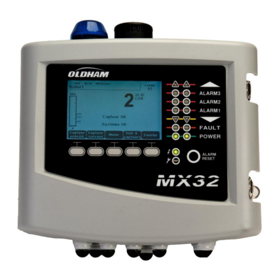
MX32v2 ANALOG AND DIGITAL CONTROLLER USER MANUAL The MX32v2 Controller Overview of the Unit External view Rep. Function Rep. Function Monochromatic, back-lit graphic Toggle Latch (one is lockable) LCD display Zone 1 status indicator Power On/Off indicator Zone 2 status indicator Failure/maintenance indicator Integrated siren (option) Contextual soft keys... - Page 18 MX32v2 ANALOG AND DIGITAL CONTROLLER USER MANUAL Internal view Figure 8: Internal view (2 line version on top and Bridge version at the bottom) Rep. Function LCD graphic display card USB programmation port On-board additional flashlight (option) Programming (or mode) selector MX32v2 in normal operation.
- Page 19 MX32v2 ANALOG AND DIGITAL CONTROLLER USER MANUAL Rep. Function Once the unit configuration or update is complete, always set back the MX32v2 selector in the "0" position. The will resume automatically. Microcontroller reset button. Press this button to reset the controller. On-board additional siren, settable from 85 to 100dB (option) CR2032 lithium battery.
- Page 20 MX32v2 ANALOG AND DIGITAL CONTROLLER USER MANUAL Rep. Function Fault and Alarms relays (2 relays are located under the power supply; tag I). From top to bottom: • Fault (Fault relay, non-configurable) • R1, R2, R3, R4 (alarm relays, configurable) Configuration of Alarm Relays COM 32 Alarm relays are to be programmed with...
-
Page 21: Front Plate
MX32v2 ANALOG AND DIGITAL CONTROLLER USER MANUAL Front Plate Figure 9: MX32v2 ’s front plate 4.2.1 LCD (A) The display shows the measurements or the settings menus. When an alarm occurs, the display turns in grayscale mode to indicate the channel that is currently displayed is on alarm. Figure 10: Display of the measurement (on the left) or parameter settings display (on the right) Menus Refer to paragraph... - Page 22 MX32v2 ANALOG AND DIGITAL CONTROLLER USER MANUAL Icon Function Orange indicator of high-range excess (OVS: overscale, high-range excess). This value is adjustable up to 110% of the range. • Off: The measurement is lower than the OVS value programmed. •...
-
Page 23: Alarm Thresholds And Relays
MX32v2 ANALOG AND DIGITAL CONTROLLER USER MANUAL Icon Function POWER Green start/stop indicator for the detectors/modules of the zone.Off: All detectors of the corresponding zone have been turned off • Solid: At least one detector of the corresponding zone is communicating •... - Page 24 MX32v2 ANALOG AND DIGITAL CONTROLLER USER MANUAL MX32v2’s Note: It is possible to modify a programmed alarm level via the user interface Program menu). 4.3.1 Internal Relays and Buzzer • Fully configurable Alarm relays are available. • 1 Fault relay is available. This relay is not configurable and is activated on the appearance of any failure.
-
Page 25: Firmplate
MX32v2 ANALOG AND DIGITAL CONTROLLER USER MANUAL (a): Automatic deactivation upon alarm disappearance even if Alarm Reset button was not pressed (b): Manual acknowledgement (press Alarm Reset) is mandatory to silence the internal buzzer Table 2: Alarms in Automatic Acknowledgement mode 4.3.4 Alarms Manual Acknowledgement In this mode, Alarms must be reset by the operator. - Page 26 MX32v2 ANALOG AND DIGITAL CONTROLLER USER MANUAL NP32V2EN Revision D.0...
-
Page 27: Digital Modules
MX32v2 ANALOG AND DIGITAL CONTROLLER USER MANUAL Digital Modules This chapter presents the digital modules that may be installed on the MX32v2 lines. The details of module connection are given on page 33.Digital modules are COM 32 configured via configuration software. Addressable Digital Modules Up to 5 modules can be used with the single line version and up to 10 modules can be used MX32v2... -
Page 28: Rs485 Transmission
MX32v2 ANALOG AND DIGITAL CONTROLLER USER MANUAL RS485 Transmission General Topology of RS 485 Network The digital modules are linked by a two twisted pair shielded cable (4 x 0.22 m² minimum, MPI-22A type, nominal impedance 100 Ohms). This cable carries the RS485 signal (A and B) on one pair and the power supply (24Vdc) on the other pair. - Page 29 MX32v2 ANALOG AND DIGITAL CONTROLLER USER MANUAL DIP switches DIP switches (ON = 1; OFF = 0) (ON = 1; OFF = 0) Table 5: Addressing table (address depends on the position of the switches) Remarks:The physical address of a module (1 to 32 max) must be identical to the registered COM 32 address via software configuration.
-
Page 30: Relay Modules
MX32v2 ANALOG AND DIGITAL CONTROLLER USER MANUAL 5.3.1 End Of Line Resistor For the last module only of each line, set switch #8 (EOL RESISTOR/RESISTANCE F.D.L.) to ON or set the jumper of the Closed Analog Input Module to (Figure 19: 8 Analog Input ModuleN). - Page 31 MX32v2 ANALOG AND DIGITAL CONTROLLER USER MANUAL A – Logic input terminalsEach of these two terminals may be connected to a voltage-free contact as per Erreur ! Source du renvoi introuvable.. B – Module configuration DIP switchesThese DIP switches are set according to the following table.
-
Page 32: 16-Logic Input Module
MX32v2 ANALOG AND DIGITAL CONTROLLER USER MANUAL . Reactivation time: If checked, time is adjustable between 15 and 900 seconds, beyond which the relay is reactivated. Controls of the alarm relay • Logic equations of up to 4 levels of parentheses by the logic operators OR, AND, NOR, and NAND. - Page 33 MX32v2 ANALOG AND DIGITAL CONTROLLER USER MANUAL 5.5.2 Introduction Ref. Description DIP switches for module configuration Power supply and RS485 network Logic inputs 1 to 16 Figure 17: 16 Logic Input Module A – DIP switchesThese DIP switches are set according to the following table: Term Symbol Slave number...
-
Page 34: 8-Analog Input Module
MX32v2 ANALOG AND DIGITAL CONTROLLER USER MANUAL 8-Analog Input Module 5.6.1 Function This digital module enables the monitoring of 8 analog inputs (4-20 mA o Wheatstone bridge) 8 analog inputs 4 wire serial cable Figure 18: 8 Analog Input Module 5.6.2 Introduction Ref.. - Page 35 MX32v2 ANALOG AND DIGITAL CONTROLLER USER MANUAL E – Module configuration DIP switchesDIP switches are set according to the following table: Term Symbol Slave number Module Address See details in the paragraph on page 22 Numéro esclave Frame filling Factory settings. Do not modify Remplissage de trame Delay Factory settings.
-
Page 36: 4-Analog Output Module
MX32v2 ANALOG AND DIGITAL CONTROLLER USER MANUAL 4-Analog Output Module Function This digital module delivers 1 to 4 discrete opto- 2 logic inputs isolated analog outputs deactivated. Several detectors can be assigned to one output allowing the management of the lowest, highest and averaged value. - Page 37 MX32v2 ANALOG AND DIGITAL CONTROLLER USER MANUAL C – Module configuration DIP switchesThese switches are set according to the following table: Term Symbol Slave number Module Address See details in the paragraph on page 22 Numéro esclave Frame filling Factory settings. Do not modify Remplissage de trame Delay Factory settings.
- Page 38 MX32v2 ANALOG AND DIGITAL CONTROLLER USER MANUAL NP32V2EN Revision D.0...
-
Page 39: Wiring And Electrical Connections
MX32v2 ANALOG AND DIGITAL CONTROLLER USER MANUAL Wiring and Electrical Connections This chapter details the electrical connections of all components of the system (MX32v2, modules, additional equipment). Controller Connection The electrical connections must be carried out by qualified personnel in compliance with the different directives in force in the country of installation. - Page 40 MX32v2 ANALOG AND DIGITAL CONTROLLER USER MANUAL The main power shall be connected to the terminal block as indicated in Figure 22. The ground conductor shall be connected to the ground terminal . Connect earth before connecting L/N conductors. Disconnect earth after disconnecting L/N conductors. Figure 22: Connection of the main power supply 6.1.3 External...
- Page 41 MX32v2 ANALOG AND DIGITAL CONTROLLER USER MANUAL 6.1.5 Digital lines The cabling of the digital lines connecting the controller to the OLCT 10N different modules deployed along the lines are the subject of the paragraphs Modules, 4- or 8-relay modules, 16-logic input modules, 8-analog input modules and 4- analog output modules of this same chapter.
- Page 42 MX32v2 ANALOG AND DIGITAL CONTROLLER USER MANUAL 6.1.7 Internal alarm relays MX32v2 has 5 internal relays: Output Function Programmable Alarm Relay Programmable Alarm Relay Programmable Alarm Relay Programmable Alarm Relay Failure :(Fault) Non-programmable common relay, energized, activated upon the presence MX32v2 of a failure in the (detector and/or module, system failure, etc.).
-
Page 43: 4- Or 8-Relay Modules
MX32v2 ANALOG AND DIGITAL CONTROLLER USER MANUAL 4- or 8-Relay Modules Supervised contact Supervised 4 or 8 output contacts DPCO (2A/250Vac-24Vdc To next MX32v2 module or previous module Figure 29: 4- or 8-relay module connections If this module is the last on the line, do not forget to set the switch marked resistor/resistance FDL to ON. -
Page 44: 8-Analog Input Module
MX32v2 ANALOG AND DIGITAL CONTROLLER USER MANUAL If this module is the last on the line, do not forget to set the switch marked resistor/resistance FDL to ON. 8-Analog Input Module MX32v2 To next module or previous module Figure 31: Connection of the 8 analog input modules (with 4-20mA detector) MX32v2 To next module Wheatstone bridge type... -
Page 45: Analog Output Module
MX32v2 ANALOG AND DIGITAL CONTROLLER USER MANUAL 4 Analog Output Module Positioned contacts Positioned contact Output Output 4-20 mA n°3 4-20 mA n°1 Output Output 4-20 mA n°2 4-20 mA n°4 MX32v2 To the next module or the previous module Figure 33: 4-analog output module connections. - Page 46 MX32v2 ANALOG AND DIGITAL CONTROLLER USER MANUAL NP32V2EN Revision D.0...
-
Page 47: Menus
MX32v2 ANALOG AND DIGITAL CONTROLLER USER MANUAL Menus General Menu Tree The following figure shows the general tree of the group of menus. See page 42 ↓ See page 44 ↓ ↓ ↓ 1 SYSTEM 2 PROGRAM 3 CALIBRATION See page 44 See page 45 See page 45 ↓... -
Page 48: Navigation Key Functions
MX32v2 ANALOG AND DIGITAL CONTROLLER USER MANUAL Navigation Key Functions Function Vertical displacement in the selected menu block. Horizontal displacement between two menu blocks. Enter Validation of the selected line. Escape Return to previous screen. Table 10: Function of the navigation keys Display in normal mode Measurement Display Figure 35: Example of the measurement display in normal mode and in grayscale mode... -
Page 49: Np32V2En
MX32v2 ANALOG AND DIGITAL CONTROLLER USER MANUAL Ref. Significance Function keys.Previous detector: Display of measurements of previous detector; scanning of all the detectors on all the lines. • Next detector: Display of measurements of next detector; scanning of all the detectors on all the lines. -
Page 50: Main Menu
MX32v2 ANALOG AND DIGITAL CONTROLLER USER MANUAL Main Menu MX32v2 This displays all the management menus of Figure 37: Main menu System ■ 1. System Info bootloader Displays the version of the program, the (internal micro- software for loading the program), and the configuration, as well as software application verifications. -
Page 51: Program
MX32v2 ANALOG AND DIGITAL CONTROLLER USER MANUAL Screen saver • OFF: no screen saver. • ON: turns into the screen saver mode (displays TELEDYNE OLDHAM SIMTRONICS logo) if no key is pressed for a certain period of time. • Averaged value •... - Page 52 MX32v2 ANALOG AND DIGITAL CONTROLLER USER MANUAL COM 32 A. Display of information described by the application: i.e., measurement range, gas detected, current detector ID and its type. Display for the current detector: • Last passed calibration: Date and time of the last calibration carried out and completed.
- Page 53 MX32v2 ANALOG AND DIGITAL CONTROLLER USER MANUAL 7.7.1 2. Start Recording • Yes: Launches the recording of calibration measurements for the selected detectors. From this moment onwards, all the calibration measurements are recorded for these detectors. “Start recording” is then displayed. The calibration of the detectors with the help of the standard gas can begin.
- Page 54 MX32v2 ANALOG AND DIGITAL CONTROLLER USER MANUAL 7.7.4 Operating mode Detector selection Select the detector to be calibrated with the help of the Previous detector and Next detector keys and press Validate. Zero calibration The Zoom command is active. Select the area of interest of the curve with the and keys. Press Zoom + up to the activation of the Zero command.
-
Page 55: Maintenance
MX32v2 ANALOG AND DIGITAL CONTROLLER USER MANUAL 7.7.5 5. Sensor exchange This function reboots the parameters (rate of wear, calibration date, internal parameters corresponding to the 4-20mA range, etc.) from the selected detector(s) following or in view of a change of cell. Detector Selection Select the detector(s) to be rebooted with the help of the Previous detector, and Next detector keys and press Select. -
Page 56: Information
MX32v2 ANALOG AND DIGITAL CONTROLLER USER MANUAL 7.8.5 4. Simulation Upon its selection, the message “The controller no longer ensures detection” is displayed. • The controller no longer keeps account of inputs (detectors, logic inputs). • The simulation measurements/status initialized current measurement/status values. - Page 57 MX32v2 ANALOG AND DIGITAL CONTROLLER USER MANUAL MX32v2 The letter “S” appears on the line if the events were obtained when the was in simulation modeDelete deletes all the data. Up to 512 events can be memorized. Beyond that, the most recent event deletes the oldest.
- Page 58 MX32v2 ANALOG AND DIGITAL CONTROLLER USER MANUAL Message Significance RELAY Status change of the designated relay. INPUT Status change of the designated input. Table 13: Relay and logic input file messages. 4. Working conditions records MX32v2 This displays the actions carried out on the (simulation mode, calibration mode, programming mode, release request, operation on internal battery), as well as the date and time of beginning and end of the event.Delete allows for the deletion of this entire monitoring...
- Page 59 MX32v2 ANALOG AND DIGITAL CONTROLLER USER MANUAL Message Significance DEAD Digital module no longer responding (line cut, module failure, wrong address, module absent). MODUL Configuration or module address error. MX32v2 TEMP+ Internal temperature of the higher than maximum tolerated value. MX32v2 TEMP- Internal temperature of the...
- Page 60 MX32v2 ANALOG AND DIGITAL CONTROLLER USER MANUAL NP32V2EN Revision D.0...
-
Page 61: Main Part Numbers
1 - red 1 - With 1 - with 3 - Wheatstone bridge 2 - Blue f.i: MX32-1-2-2-2-1-1-0-1 for MX32 1 channel, 100/240Vac, English, Blue strobe and horn, RS 485 output and COM 32 software Description Reference Image 8 Analog Input Module... - Page 62 MX32v2 ANALOG AND DIGITAL CONTROLLER USER MANUAL Description Reference Image RS485 commnication board 6 451 680 100-240Vac/24Vdc Power Supply 6 314 210 Fuse F7 (4A time-delay, 8.4A for 120 6 154 738 seconds - 250Vac) CR2032 lithium battery 6 111 321 340 mA programming strip (8 maximum 6 353 442 per analog input module), see Figure 19...
-
Page 63: Cleaning And Maintenance
(see Chapter 8 for the list of spare parts). The controller must be first switched off. Power on the controller once the battery has been replaced. TELEDYNE OLDHAM SIMTRONICS does not allow any other repairs than those listed here above. - Page 64 MX32v2 ANALOG AND DIGITAL CONTROLLER USER MANUAL NP32V2EN Revision D.0...
-
Page 65: 10 Certificate Of Compliance
MX32v2 ANALOG AND DIGITAL CONTROLLER USER MANUAL 10 Certificate of Compliance The document hereafter (2 page) reproduces the EU declaration of conformity. NP32V2EN Revision D.0... - Page 66 MX32v2 ANALOG AND DIGITAL CONTROLLER USER MANUAL NP32V2EN Revision D.0...
- Page 67 MX32v2 ANALOG AND DIGITAL CONTROLLER USER MANUAL NP32V2EN Revision D.0...
- Page 68 MX32v2 ANALOG AND DIGITAL CONTROLLER USER MANUAL NP32V2EN Revision D.0...
-
Page 69: 11 Technical Specifications
MX32v2 ANALOG AND DIGITAL CONTROLLER USER MANUAL 11 Technical Specifications 11.1 MX32v2 Controller Function Function Gas Detection Controller Number of lines 1 or 2 as per model Display and indicators Display Back-lit graphic LCD Status indicators - 7 LEDs for each of the 2 lines - 1 Power On/Off visual indicator - 1 General failure indicator Keys... - Page 70 MX32v2 ANALOG AND DIGITAL CONTROLLER USER MANUAL Electrical characteristics ■ AC power supply 100 to 240Vac, 50/60 Hz ■ Maximum 24Vdc output current 1.5A with derating (see next page) ■ DC power supply 22 to 28Vdc ■ Maximum power consumption 3.5A @ 24Vdc. 1.5A per line and rest is for controller consumption Mechanical characteristics ■...
- Page 71 MX32v2 ANALOG AND DIGITAL CONTROLLER USER MANUAL Measurement Lines ■ Digital lines 2 maximum ■ RS485 Modbus, 9600 Bauds ■ 4 wire serial cable, 2 shielded twisted pairs (1 for the line and 1 for communication) ■ Analog lines 2 maximum ■...
-
Page 72: Relay Module
MX32v2 ANALOG AND DIGITAL CONTROLLER USER MANUAL 11.2 Relay Module Function Function Management of 4 or 8 relays from the digital signals issued by MX32v2 ■ Number of relays 4 or 8 relays ■ DPCO contact relays ■ Relay type Bistable ■... -
Page 73: 8-Analog Input Module
MX32v2 ANALOG AND DIGITAL CONTROLLER USER MANUAL 11.4 8-Analog Input Module Function Function 4-20mA detector or Wheatstone bridge connections Capacity 1 to 8 independent inputs ■ Terminals Screw terminals. Can accept 2.5 mm² (14AWG) wire ■ Removable terminal without powering the line down Consumption 53 mA max (detector excluded) Assembly... - Page 74 MX32v2 ANALOG AND DIGITAL CONTROLLER USER MANUAL NP32V2EN Revision D.0...
-
Page 75: 12 Rs485 Digital Output
MX32v2 ANALOG AND DIGITAL CONTROLLER USER MANUAL 12 RS485 Digital Output MX32v2 RS485 Modbus units using the option are equipped with a communication card (code 6451680), which is affixed to the motherboard. This card generates a RS485 output in Modbus RTU format. -
Page 76: Transfer Table
MX32v2 ANALOG AND DIGITAL CONTROLLER USER MANUAL 12.2 Transfer Table Two types of information can be retrieved the RS485 output: • Information about sensor configuration; • Real-time sensor information (measurements, alarms, etc.). 12.2.1 1. Access to configuration information It is possible to access the installation configuration (for example, to access the alarm thresholds or the names of the sensors). -
Page 77: Address Table
MX32v2 ANALOG AND DIGITAL CONTROLLER USER MANUAL Example Access to measurements from the sensor located at line 2 and address 32 of unit n° 2. A. Determination of the sensor address: (2 – 1) x 32 + 32 = 64 Modbus B. - Page 78 MX32v2 ANALOG AND DIGITAL CONTROLLER USER MANUAL 12.3.2 Configuring sensors Downloading the configuration MX32v2 uses 64 external addresses (line #1 channel #1, to line #2 channel #32) and 2 analog channels for which the addresses are located from 257 to 258. Modbus With the automated system, it is possible to send 66 (64 + 2) requests, where the...
- Page 79 MX32v2 ANALOG AND DIGITAL CONTROLLER USER MANUAL Address SENSORS Data type [64 + 2] bytes Com sensor Unicode text (16 bits) 16 characters including the final /0. Status Start / Stop: if in operation, variable = 1. If stopped, variable = 0. Gas name Unicode text (16 bits) 20 characters including the...
- Page 80 MX32v2 ANALOG AND DIGITAL CONTROLLER USER MANUAL Address SENSORS Data type [64 + 2] bytes Value Overscale -999 to 9999 (real value to threshold be multiplied like the range) Default low Value -999 to 9999 (real value to threshold be multiplied like the range) Out of range Value -999 to 9999 (real value to...
- Page 81 MX32v2 ANALOG AND DIGITAL CONTROLLER USER MANUAL 12.3.3 Acquisitions retrieved cyclically Real address SENSOR Nb bytes Data type MEASUREME NTS [256 + If digital Sensor Table with 66 signed integer of 16 bits where measurement the measurements are listed at their address. Start: 2001 The measurement being whole, the automatic...
- Page 82 MX32v2 ANALOG AND DIGITAL CONTROLLER USER MANUAL NP32V2EN Revision D.0...
-
Page 83: Specific Conditions Of Use And Functional Safety
MX32v2 ANALOG AND DIGITAL CONTROLLER USER MANUAL 13 Specific conditions of use and Functional Safety 13.1 Reliability data MX32v2 controller certified according European standard 50271:2010 “Electrical apparatus for the detection and measurement of combustible gases, toxic gases or oxygen. Requirements and tests for apparatus using software and/or digital technologies”. -
Page 84: Specific Instructions For The Prevention Of Explosions According To Atex 2014/34/Eu European Directive
MX32v2 controller is digitally compatible with OLCT 10N, OLCT 80, OLCT 710, iTrans2, 700 and Meridian gas detectors. • In the event the user connects a non-TELEDYNE OLDHAM SIMTRONICS brand detector MX32v2 to the controller, the user must ensure that the detector is compatible with the input characteristics of the controller, so that the information delivered by the detector will be properly interpreted (see transfer curve on the following page). - Page 85 Connecting detectors other than detectors to the controller Any user wishing to use detectors other than TELEDYNE OLDHAM SIMTRONICS detectors must ensure that they are compatible with the controller, in order the complete installation to be considered as a safety device.
- Page 86 MX32v2 ANALOG AND DIGITAL CONTROLLER USER MANUAL NP32V2EN Revision D.0...
- Page 87 MX32v2 ANALOG AND DIGITAL CONTROLLER USER MANUAL NP32V2EN Revision D.0...
- Page 88 Road TX 77381, USA 62027 ARRAS Cedex, Shanghai Free Trade Zone Tel.: +1-713-559-9200 France China Tel.: +33 (0)3 21 60 80 80 Tel.: +86-134-8229-5057 www.teledynegasandflamedetection.com © 2020 Teledyne Oldham Simtronics. All right reserved. NP32V2 EN Revision D.0. / October 2020...
Need help?
Do you have a question about the MX32 and is the answer not in the manual?
Questions and answers